
Generalized constraint collection management method

a collection management and constraint technology, applied in the field of electronic circuit design, can solve the problems of affecting the productivity of designers, corresponding increase in the number, complexity and specialization of constraints available to designers, and scripts often fail to accommodate continuous incremental changes to constraints

Active Publication Date: 2008-03-27
CADENCE DESIGN SYST INC
View PDF19 Cites 41 Cited by
  • Summary
  • Abstract
  • Description
  • Claims
  • Application Information

AI Technical Summary

Benefits of technology

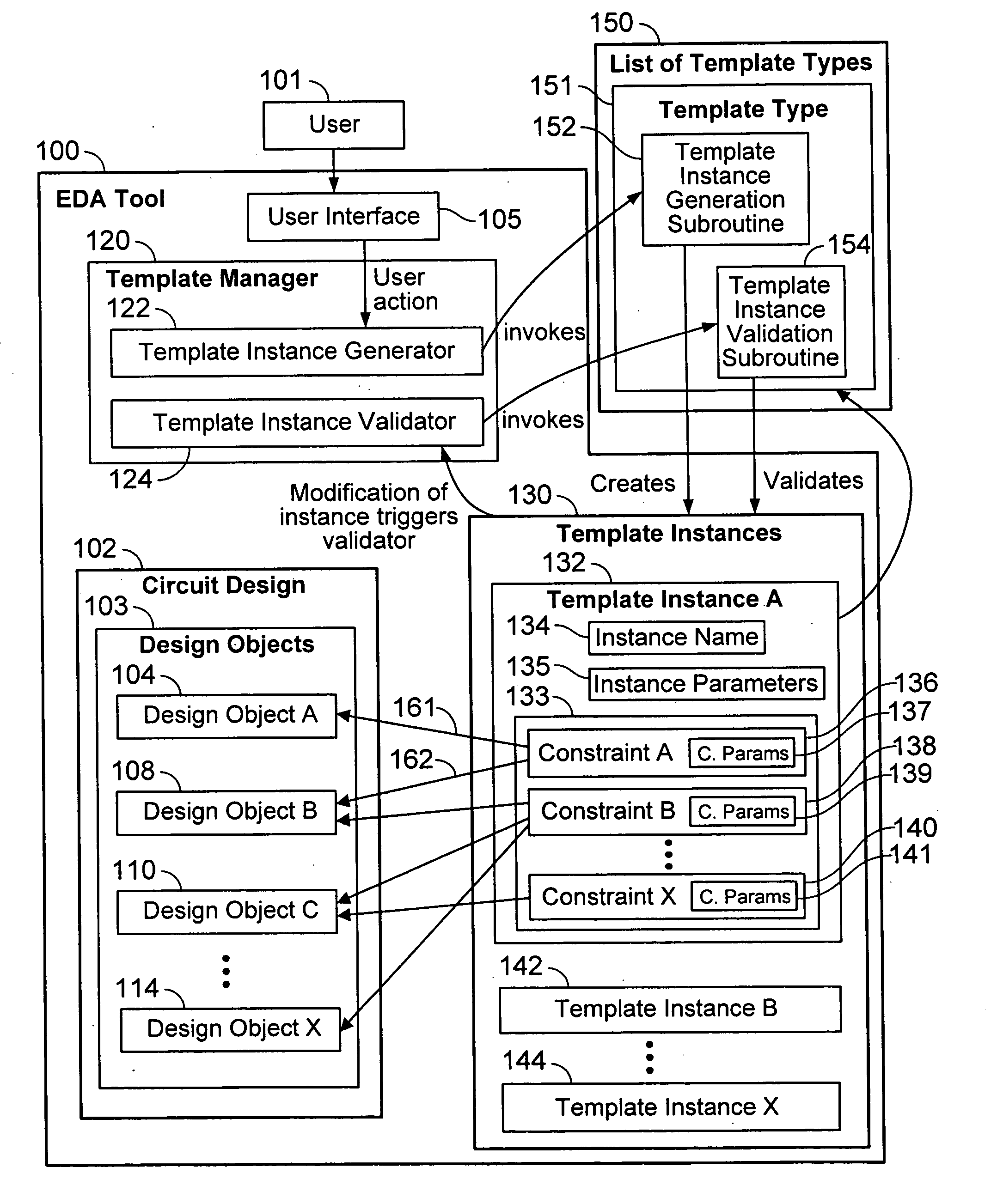
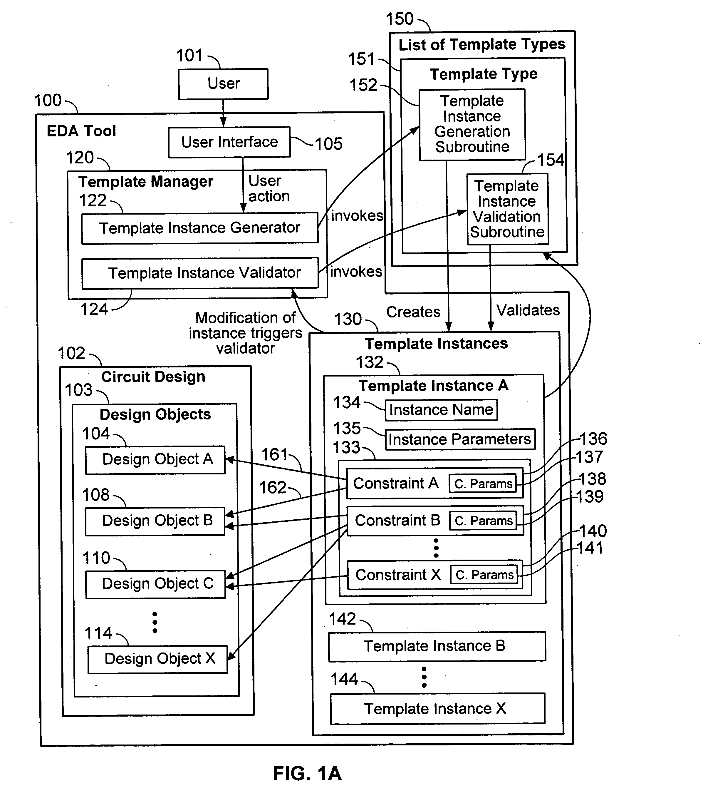
The invention is about a method and system for automatically applying constraints to design objects in a circuit design created using an electronic design automation tool. The method involves receiving a selection of a circuit design object and a template type, identifying a template instance generation process associated with the template type, and invoking the process to create a template instance. The template instance is then associated with the circuit design object to represent that the constraint applies to it. The system includes a design object selector, a template type selector, and a template instance producer to automate the application of constraints. The technical effect of the invention is to simplify the process of applying constraints to circuit designs, making it easier for designers to create and test new designs.

Problems solved by technology

However, as more constraint-driven algorithms become available, there is a corresponding increase in the number, complexity, and specialization of constraints that are available to the designer.
Unfortunately, the designer's productivity can be impeded by time spent selecting and entering the appropriate constraints.
However, the scripts often fail to accommodate continuous incremental changes to the constraints.
Unfortunately, using existing change methodologies to change scripts can be error-prone, because, for example, an operator may enter incorrect constraints, or a script that generates constraints may contain an error that may introduce incorrect or inconsistent constraints.
With this group-based approach, multiple constraints can be entered at once, e.g., in response to one user action, so the constraint entry process is somewhat simplified, but such techniques still require restarting the constraint entry task from scratch for new technology or new constraint driven tools and are, therefore, subject to technological obsolescence.
Therefore, the constraints, associated instructions, and circuit designs that use the constraints should not ordinarily be accessible by other users, or by the EDA tool vendor, for example.

Method used


Image

  • Generalized constraint collection management method
  • Generalized constraint collection management method
  • Generalized constraint collection management method

Examples


Embodiment Construction

[0038]The following description is presented to enable any person skilled in the art to make and use the invention, and is provided in the context of particular applications and their requirements. Various modifications to the preferred embodiments will be readily apparent to those skilled in the art, and the generic principles defined herein may be applied to other embodiments and applications without departing from the spirit and scope of the invention. Moreover, in the following description, numerous details are set forth for the purpose of explanation. However, one of ordinary skill in the art will realize that the invention might be practiced without the use of these specific details. In other instances, well-known structures and devices are shown in block diagram form in order not to obscure the description of the invention with unnecessary detail. Thus, the present invention is not intended to be limited to the embodiments shown, but is to be accorded the widest scope consist...


PUM


Abstract

Techniques are provided to allow users of Electronic Design Automation (EDA) tools to define constraint template types for efficiently associating constraints with design objects to specify design intent. Processes for creating and validating the constraints are provided by user-defined plug-ins, thereby allowing users to annotate circuit designs with constraints for proprietary layout and fabrication processes without exposing the constraints to tool vendors or competitors. The constraints are re-created from the template types whenever the circuit design is loaded into the EDA tool, so that the constraints are based upon the latest version of the template type. The constraints are also re-created when validation fails. Constraint groups are reusable in different designs, technology nodes, and processes because they automatically expand to provide the specific constraints to achieve a goal. The specific constraints in a template type can be modified as technology changes, and the modification will automatically be applied to the design objects.

Description

BACKGROUND OF THE INVENTION[0001]1. Field of the Invention[0002]The invention relates to the design of electronic circuits and more particularly to association of constraints with design objects in electronic circuit designs.[0003]2. Description of the Related Art[0004]Electronic Design Automation (EDA) tools are software programs that are used to design electronic circuits. A suite or combination of EDA tools may be used to convert a circuit design idea to a physical design including logic gates, circuit components, and their interconnections. A circuit designer typically uses an EDA tool to create a schematic design of a circuit. The designer may use another EDA tool from the suite to convert the schematic to a physical circuit layout, which includes the shapes, positions, and dimensions of semiconductor and conductor materials such as silicon and metal. The EDA design tool in essence translates the schematic design to a physical layout using layout rules, which specify, for examp...

Claims


Application Information

Patent Timeline
Patent Type & Authority Applications(United States)
IPC IPC(8): G06F17/50
CPCG06F17/5045G06F30/30
Inventor ARSINTESCU, GEORGE B.
Owner CADENCE DESIGN SYST INC
Learn More