
Method and apparatus for controlling engine operation during regeneration of an exhaust aftertreatment system

a technology of exhaust aftertreatment and engine operation, which is applied in the direction of mechanical equipment, engines, machines/engines, etc., can solve the problems of increased engine brake mean-effective pressure, engine roughness, and second pressure spike, so as to optimize fuel consumption, reduce calibration parameters and calibration effort, and deliver engine torque more quickly

Inactive Publication Date: 2008-04-03
GM GLOBAL TECH OPERATIONS LLC
View PDF5 Cites 28 Cited by
  • Summary
  • Abstract
  • Description
  • Claims
  • Application Information

AI Technical Summary

Benefits of technology

[0007]There is provided a method, preferably executed as a computer program in a control module for an engine system, for controlling operation of the internal combustion engine. This comprises controlling post-injection of fuel into a combustion chamber effective to regenerate an exhaust aftertreatment device. Main fuel injection into each combustion chamber is selectively controlled effective to maintain engine output torque.
[0008]B

Problems solved by technology

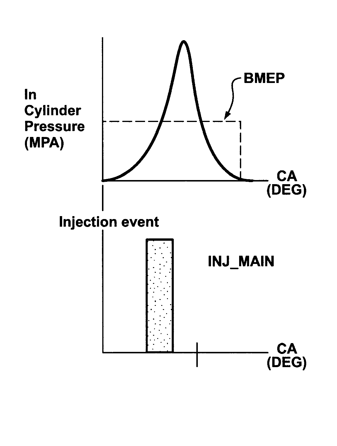
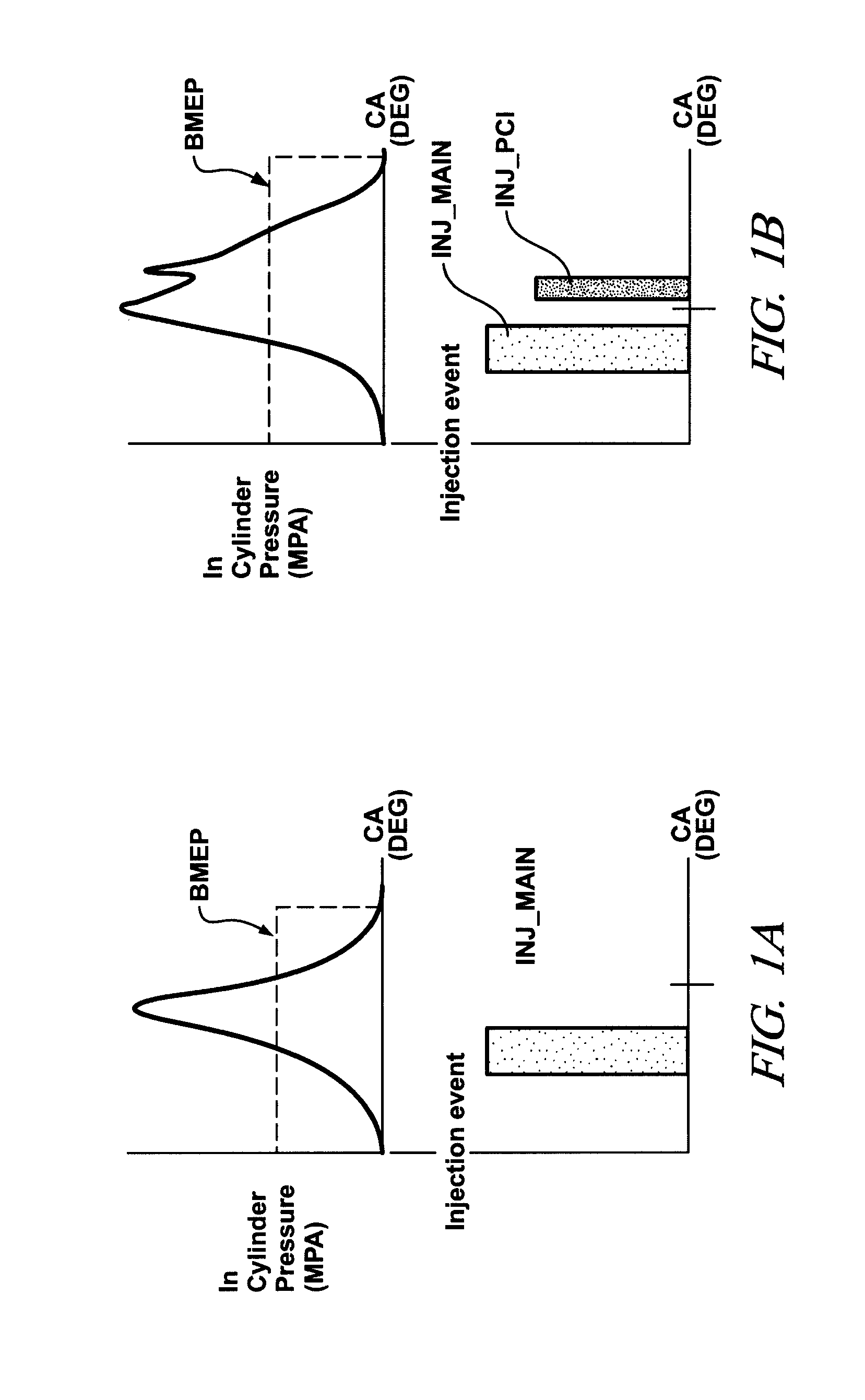
As shown by comparing the in-cylinder pressures in the figures, post-injection of fuel typically results in a second pressure spike and an increase in engine brake mean-effective-pressure.
However, such calibration requires extensive testing and analysis, and may not result in reduced engine roughness during real vehicle driving conditions due to the amount of fuel being injected post-combustion is typically adjusted according to real-time catalyst temperatures and inlet air-fuel ratio.
Furthermore, the main injection typically causes a drop in fuel injection line pressure which may not have recovered at the time of post-injection of fuel following the main fuel injection.
Therefore, torque contribution caused by post-injection may not be consistent with a predetermined calibration torque.

Method used


Image

  • Method and apparatus for controlling engine operation during regeneration of an exhaust aftertreatment system
  • Method and apparatus for controlling engine operation during regeneration of an exhaust aftertreatment system
  • Method and apparatus for controlling engine operation during regeneration of an exhaust aftertreatment system

Examples


Embodiment Construction

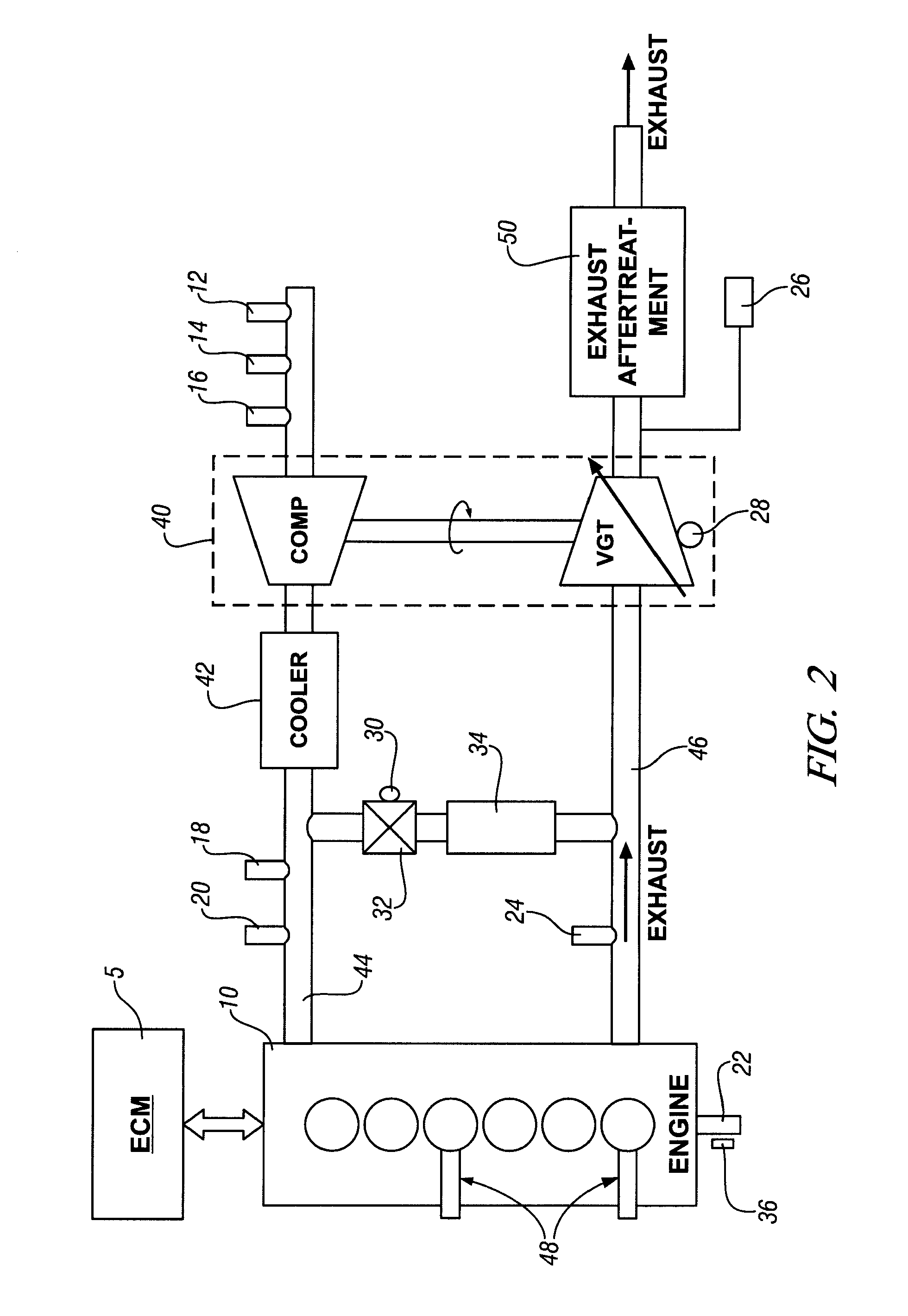
[0014]Referring now to the drawings, wherein the showings are for the purpose of illustrating the invention only and not for the purpose of limiting the same, FIG. 2 depicts an engine 10, engine control module (ECM) 5, and exhaust aftertreatment system 50 which has been constructed in accordance with an embodiment of the present invention. The exemplary engine 10 comprises a conventional multi-cylinder internal combustion engine mechanized to operate at a lean air / fuel ratio, shown as a compression-ignition configuration, although this invention is not meant to be limited to compression-ignition engine configurations. Engine system components include an exhaust gas recirculation (EGR) valve 32 and cooler 34, an intake manifold 44, and an exhaust manifold 46. The exhaust aftertreatment system 50 comprises devices, taken individually or in combination, operative to convert constituent elements of the exhaust gas feedstream to harmless gases, including, e.g., a diesel particulate filte...


PUM


Abstract

There is provided a method and apparatus for controlling operation of an internal combustion engine, comprising controlling engine torque during regeneration of an exhaust aftertreatment system. This comprises controlling post-injection of fuel into a combustion chamber effective to regenerate an exhaust aftertreatment device. Main fuel injection into each combustion chamber and boost are selectively controlled effective to maintain engine output torque.

Description

TECHNICAL FIELD[0001]This invention pertains generally to internal combustion engines, and related to controlling engine operation during exhaust aftertreatment regeneration.BACKGROUND OF THE INVENTION[0002]Modern internal combustion engines are equipped with sophisticated systems to monitor and control various aspects of engine performance during ongoing operation to meet operator demands for performance, including torque and fuel economy, and to satisfy government regulations related to emissions, safety, and fuel economy. Engine systems operable at lean air / fuel ratios, including diesel engines and homogeneous-charge engines, are effective to achieve operator demands. Such engine systems utilize exhaust aftertreatment systems comprising diesel particulate filters (DPF), NOx traps (LNT), NOx adsorbers, and selective catalyst reduction (SCR) devices, either alone or in combination.[0003]An exhaust aftertreatment device can require regeneration during its service life to maintain pe...

Claims


Application Information

Patent Timeline
IPC IPC(8): F01N5/04F01N3/00F02D23/00
CPCY02T10/20F01N3/00Y02T10/12
Inventor WANG, YUE-YUNHASKARA, IBRAHIM
Owner GM GLOBAL TECH OPERATIONS LLC
Learn More