
Cleaning device for paint rollers

a technology of cleaning device and paint roller, which is applied in the direction of cleaning process and apparatus, cleaning using liquids, chemistry apparatus and processes, etc., can solve the problems of related or known devices, manual and messy process of their use, and paint would be washed out, so as to eliminate the possibility of rust and corrosion

Inactive Publication Date: 2008-04-03
HOFFMANN TERRY A
View PDF18 Cites 25 Cited by
  • Summary
  • Abstract
  • Description
  • Claims
  • Application Information

AI Technical Summary

Benefits of technology

[0020]Cleaning Solution and Operating Force: The device will be operated using water as the operating force. The device should be non-electrical in order to eliminate possibility of electrical shock and need for an Underwriters Laboratory (U.L.) label. A supply of water is accessible and convenient. It also provided with sufficient pressure to operate the device. The cleaning solution for water soluble paints is obviously water. Under sufficient pressure, soap would not be necessary to properly clean a paint roller.
[0024]Materials: As much of the device should be manufactured from plastic and aluminum to eliminate possibility of rust and corrosion. It is, therefore, the principle object of this invention to provide a cleaning device for paint rollers, and which is very affective in cleaning paint deep from within the nap of a roller and then semi-automatically spin dry the same after cleansing.

Problems solved by technology

After considerable usage, for a length of time, eventually the paint would be washed out.
Furthermore, the process of its usage was manual and messy.
Other investigations have not found any related or known device for use for washing water soluble paint manually or automatically from a paint roller.
Usage of any type of an apparatus to clean oil based paint from a paint roller is just not economical.
It would require the usage of too much paint thinner to remove all the paint from the nap of the roller.

Method used


Image

  • Cleaning device for paint rollers
  • Cleaning device for paint rollers
  • Cleaning device for paint rollers

Examples


Embodiment Construction

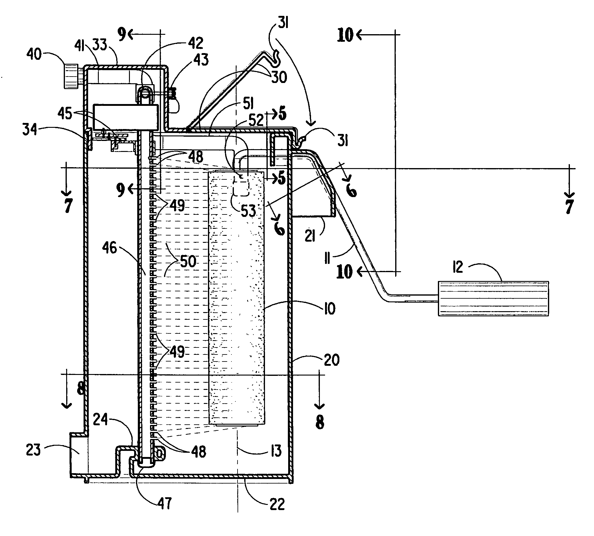
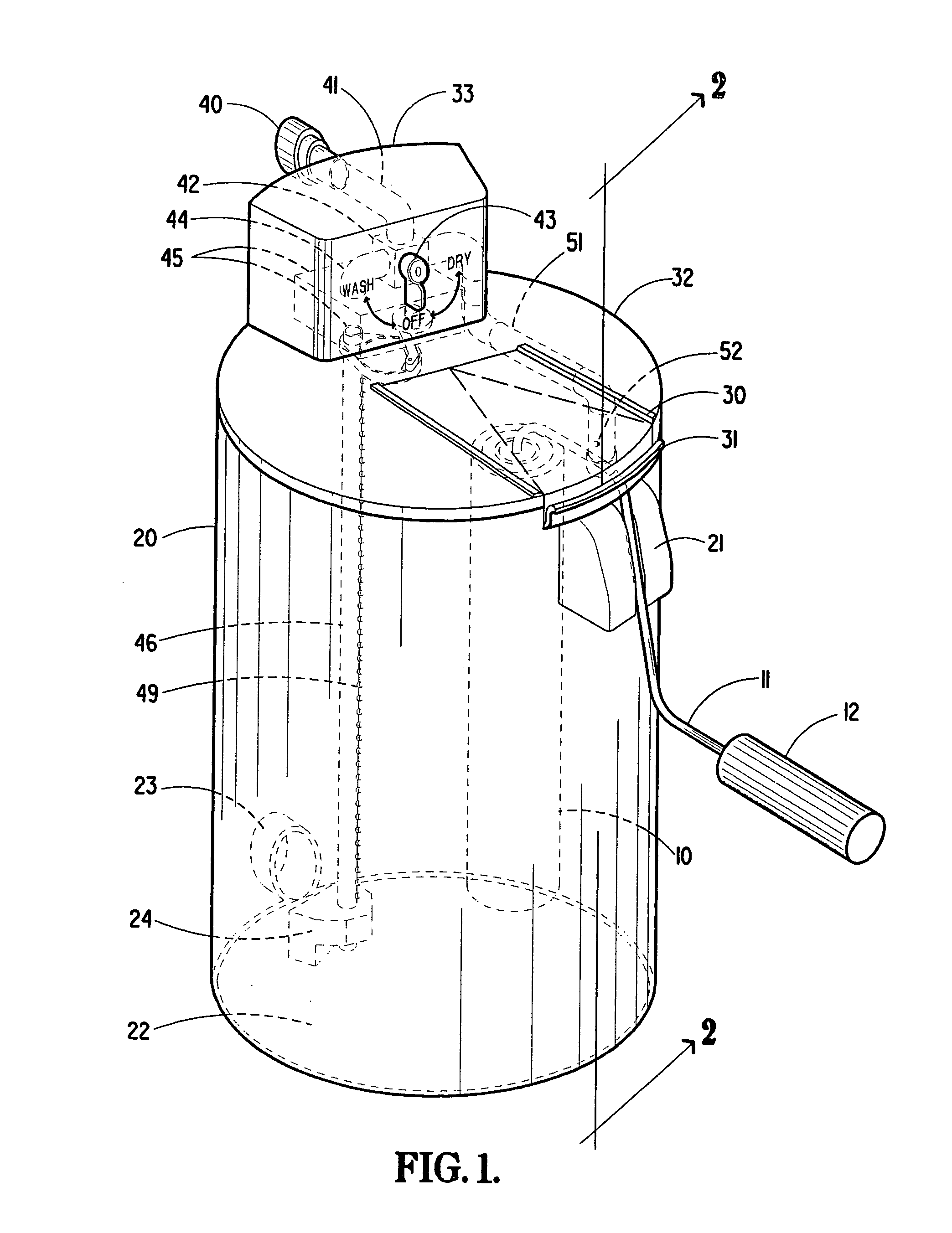
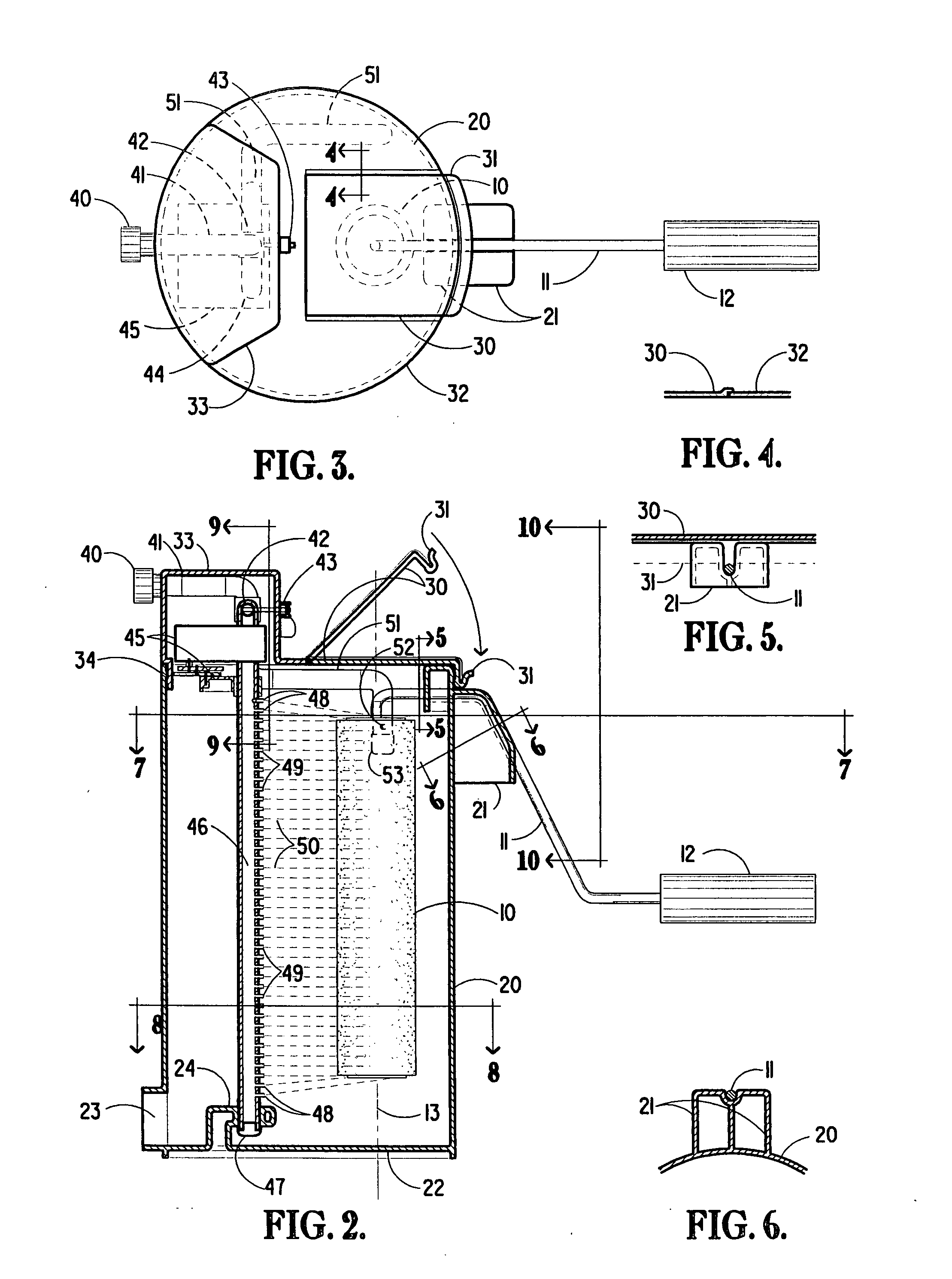
[0045]Referring now to isometric view FIG. 1, a paint roller cleaner in accordance with my invention is illustrated showing a paint roller 10 attached to a roller handle 11 and a handle grip 12 inserted into the apparatus. The apparatus consists of an upper cover 32 attached to a lower casing 20.

[0046]The upper cover 32 consists of a hinged lid 30 which is large enough to receive the paint roller 10 and paint roller handle 11 with a snap lip latch 31 that locks down the lid to the lower casing 20 and also secures the paint roller handle 11 in a grooved bracket 21. Integral to the upper cover is the operating mechanism housing 33 imprinted with WASH-OFF-DRY around the three-way valve lever 43. On the back of the housing 33 is a water coupling connector 40 that connects to the water supply tubing 41. The water supply tubing connects to a three-way valve 42 that is controlled by a lever 43. The three-way valve performs three functions. The first function is to shut off the flow of wate...


PUM


Abstract

Paint rollers may be cleaned of water soluble paints within this apparatus which is comprised of an enclosed housing with a drain at the bottom which also contains an oscillating water manifold the length of the roller which produces a series of water jets aligned with the elongated axis of the housing which impact the paint roller starting at a tangent to the roller so as to impart a spin. The water manifold oscillates aligned with the elongated axis of the roller from the tangent to a center of roller that slows the spin of the roller which oscillates to the opposite tangent of the roller and which spins the roller in the opposite direction. The enclosed housing also contains a single jet of water aligned near the top of the roller and at a tangent to the roller which impacts the paint roller starting at a tangent to the roller so as to impart a spin. The single water jet and the oscillating water jets are connected to a three-way valve which sends water to either the oscillating water manifold, the single water jet or shuts off the flow of water entirely. An opening with a hinged lid at the top of the enclosed housing allows the insertion of the paint roller. A clamping means is located on the outside of the housing on the side opposite the location of the oscillating water manifold and single fixed water jet which adapts to a variety of paint roller holder rods in order that the paint roller itself may be properly align the roller parallel to the oscillating water manifold within the housing. The water jets on the oscillating water manifold impact off-center on the pile of the paint roller, washing out the water soluble paint, and imparting a spin on the roller which throws out the diluted paint and the wash water. As the water manifold oscillates to the center of the paint roller, the rotation of the paint roller decreases and forces water deep into the pile of the paint roller that will dilute the paint. As the oscillating water manifold passes the center of the roller, the roller starts to spin in the opposite direction imparting a spin on the roller that throws out the diluted paint and wash water from deep within the pile of the paint roller.

Description

CROSS REFERENCE TO RELATED APPLICATION[0001]This non-provisional application claims priority to provisional application Ser. No. 60 / 847,879 filed on Sep. 28, 2006.BACKGROUND OF THE INVENTION[0002]This invention relates to a device useful for cleaning wet water soluble paint from a paint roller. This invention eliminates the messy operation of cleaning a paint roller of water soluble paint after its usage, which normally scatters cleaning water filled with paint residue extensively, during a cleaning operation.[0003]Since the cost of a paint roller varies between $2.00-$12.00, in the retail market, the idea of being able to effectively clean and reuse a high quality roller is desirable. The average price of a reusable roller is normally within the range of $8.00. Thus, the application of a cleaning device to keep a roller relatively free of residue paint, after its usage, is desirable.[0004]After reviewing the products in the market, it appears that the only manufactured product to w...

Claims


Application Information

Patent Timeline
IPC IPC(8): B08B3/02B08B13/00
CPCB44D3/006
Inventor HOFFMANN, TERRY A.
Owner HOFFMANN TERRY A
Learn More