Hybrid Vehicle with Camless Valve Control

a technology of camless valve control and hybrid vehicles, applied in the direction of engine starters, machines/engines, output power, etc., can solve the problems of increasing parasitic losses during electric-only operation and source of inefficiency

Inactive Publication Date: 2008-04-03
FORD GLOBAL TECH LLC
View PDF15 Cites 50 Cited by
  • Summary
  • Abstract
  • Description
  • Claims
  • Application Information

AI Technical Summary

Problems solved by technology

As this torque serves only to start the engine and does not aid in propelling the vehicle, it is a source of inefficiency.
Compression and expansion of cylind

Method used


Image

  • Hybrid Vehicle with Camless Valve Control
  • Hybrid Vehicle with Camless Valve Control
  • Hybrid Vehicle with Camless Valve Control

Examples


Embodiment Construction

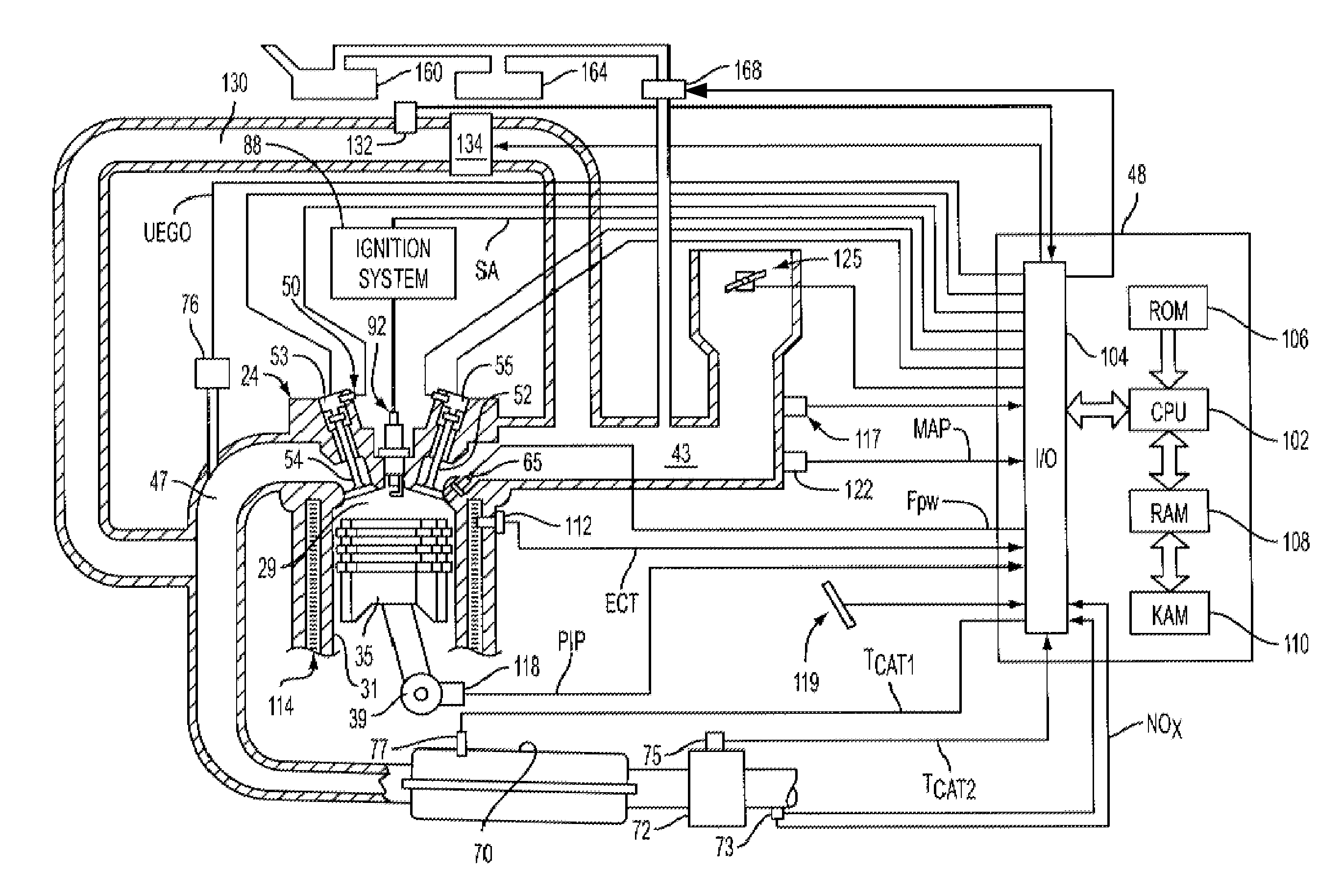
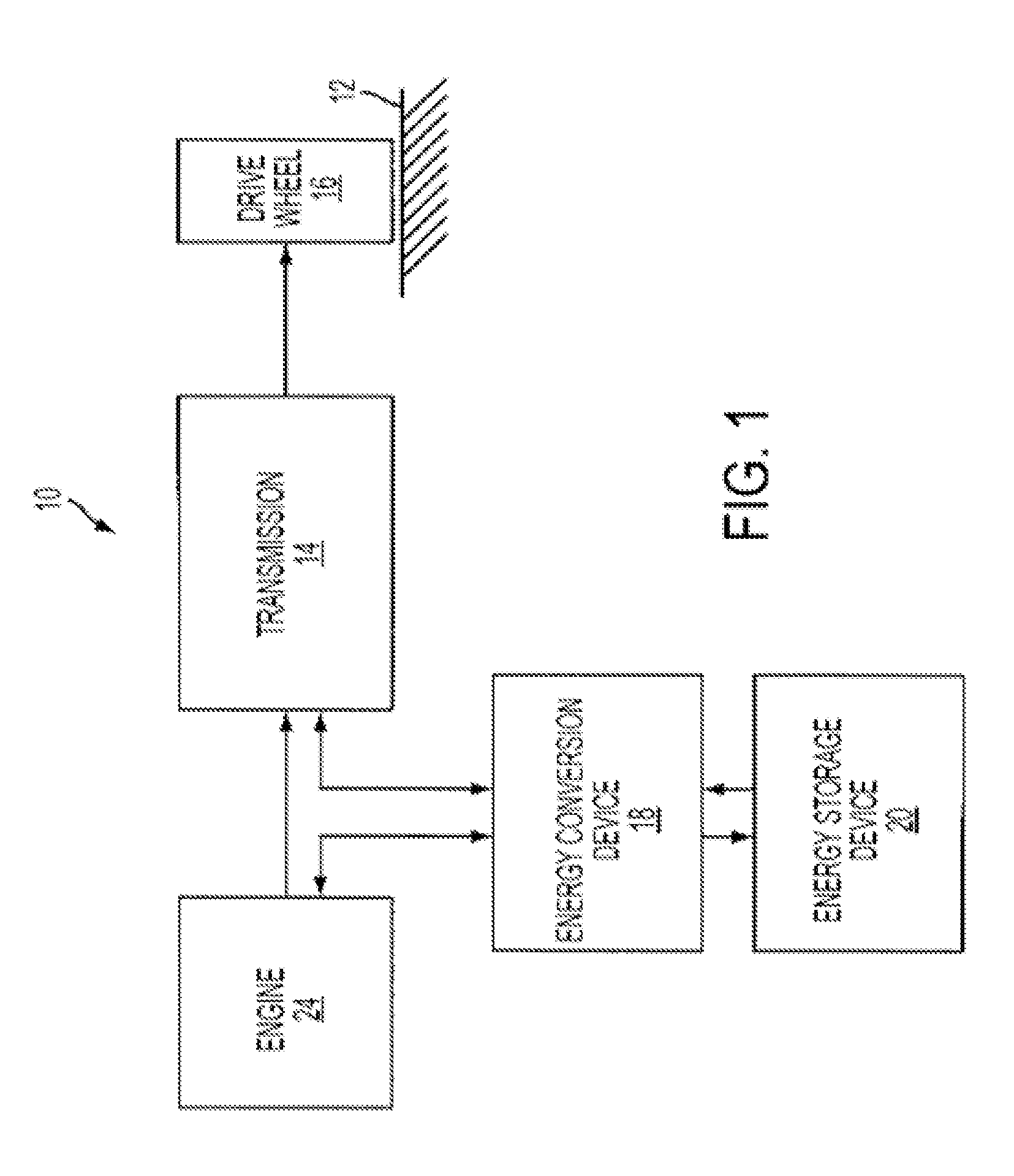
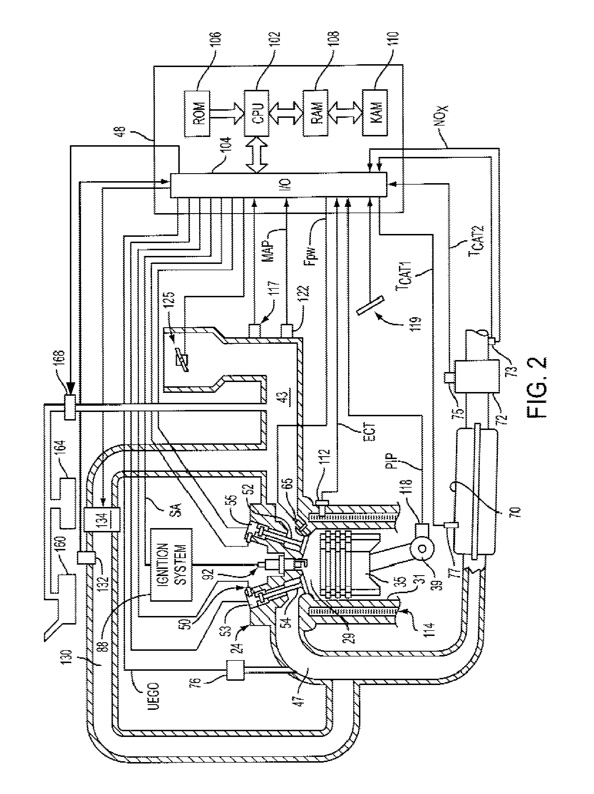
[0009]Referring to FIG. 1, the figure schematically depicts a vehicle with a hybrid propulsion system 10. Hybrid propulsion system 10 includes an internal combustion engine 24, further described herein with particular reference to FIG. 2, coupled to transmission 14. Transmission 14 may be a manual transmission, automatic transmission, or combinations thereof. Further, various additional components may be included, such as a torque converter, and / or other gears such as a final drive unit, etc. Transmission 14 is shown coupled to drive wheel 16, which in turn is in contact with road surface 12.

[0010]In this example embodiment, the hybrid propulsion system also includes an energy conversion device 18, which may include a motor, a generator, among others and combinations thereof. The energy conversion device 18 is further shown coupled to an energy storage device 20, which may include a battery, a capacitor, a flywheel, a pressure vessel, etc. The energy conversion device can be operate...


PUM


Abstract

A method of controlling a hybrid propulsion system of a vehicle, where the hybrid propulsion system includes an internal combustion engine and an alternate torque source configured to provide motive power to the vehicle. While the engine is turned off, initial cranking of the engine is performed to initiate an engine start. During initial cranking, a cylinder valve is operated in a startup timing mode so as to reduce pumping work required to move a piston during initial cranking. Subsequent to initial cranking, the valve is operated with a different timing than that employed during the startup timing mode.

Description

BACKGROUND AND SUMMARY[0001]Research and commercialization of vehicles with hybrid propulsion systems has increased substantially in recent years. Hybrid-electric vehicles (HEV) in particular have been successfully introduced into the marketplace, and are expected to capture substantial increases in market share in coming years. HEV vehicles may be configured in a variety of ways. Typical configurations include a battery or other energy storage device, and a motor / generator or other mechanism for converting mechanical energy of the vehicle into electrical energy stored in the battery, and / or for using the electrical energy stored in the battery to generate torque for propelling the vehicle.[0002]HEV vehicles typically are capable of operating in different propulsion modes. For example, some HEV vehicles may be operated with the internal combustion engine turned on or turned off. In these vehicles, various control schemes are employed to control whether the engine is turned on or off...

Claims


Application Information

Patent Timeline
IPC IPC(8): B60K6/00
CPCB60W10/06Y02T10/6286B60W20/00B60W2710/0616F02B1/12F02B23/104F02B2075/125F02D13/0215F02D17/02F02D29/02F02M25/0752F02M25/0754F02M25/0756F02M25/089F02N19/004Y02T10/121B60W10/08B60K2006/268F02M26/01F02M26/47F02M26/48Y02T10/62B60K6/24
Inventor ORTMANN, WALTKONEDA, PHILIPKRASKA, MARVINMEGLI, THOMAS
Owner FORD GLOBAL TECH LLC
Why Eureka
Try Eureka