Insulated package insert apparatus and method

Inactive Publication Date: 2008-04-03
CUTTING EDGE CONVERTED PROD
View PDF21 Cites 2 Cited by
  • Summary
  • Abstract
  • Description
  • Claims
  • Application Information

AI Technical Summary

Benefits of technology

[0008]Compatible and attuned with the present invention, an insulated package insert free of pouches to optimize a fit of the insert to a

Problems solved by technology

Folding the flat sheet of insulating material into the desired shape results in formation of gusseted pouches of superfluous insulating material.
The pouches can interfere with the fit of the insert to the associated container.
The process of securing the pouches increases the cost of manufacturing.
Additionally, the adhesive strip may be damaged or lost during use, thereby allowing the pouches to become separated from sec

Method used


Image

  • Insulated package insert apparatus and method
  • Insulated package insert apparatus and method
  • Insulated package insert apparatus and method

Examples


Embodiment Construction

[0020]The following detailed description and appended drawings describe and illustrate an exemplary embodiment of the invention. The description and drawings serve to enable one skilled in the art to make and use the invention, and are not intended to limit the scope of the invention in any manner. In respect of the methods disclosed, the steps presented are exemplary in nature, and the order of the steps is not regarded as necessary or critical.

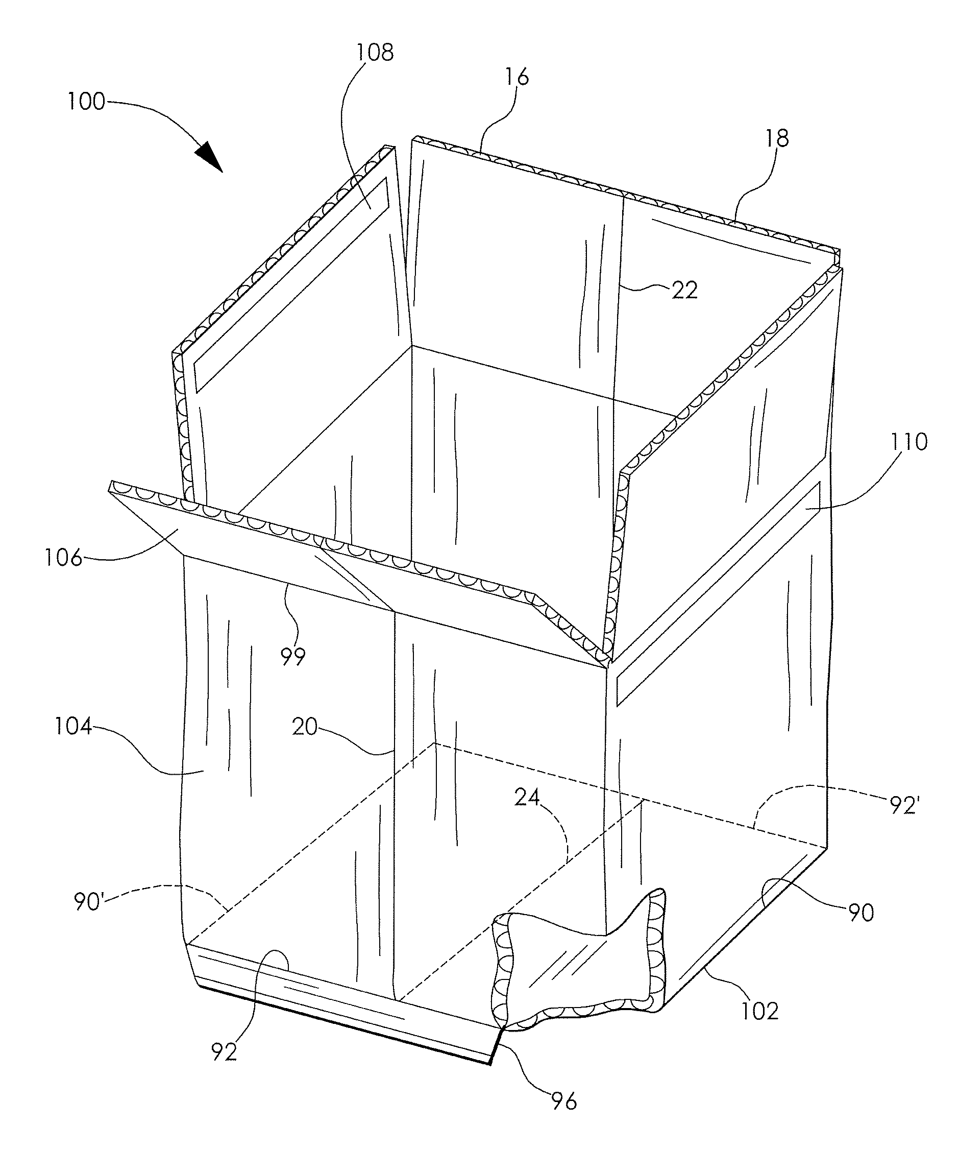
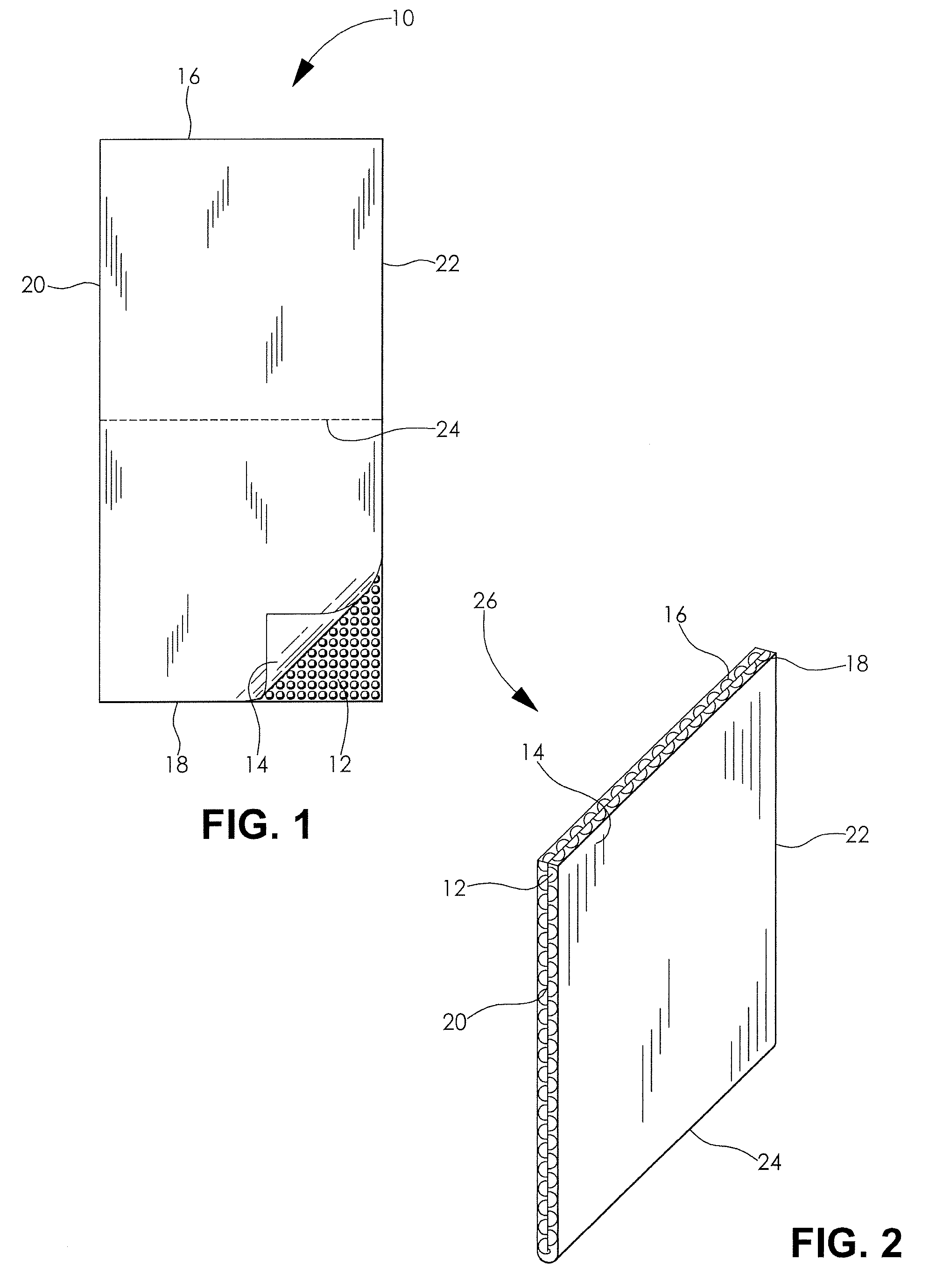
[0021]Referring now to the drawings and in particular to FIG. 1, a substantially planar rectangular blank of material 10 is shown. The blank 10 is employed to form an insert 100, shown in FIG. 7. The insert 100 is designed to be removably received in a container, such as corrugated box, to provide a substantially fluid tight insulated lining to the container. The blank of material 10 is a deformable laminate having a layer 12 of a bubble pack material or air bubble cushioning material and a superposed layer 14 of metallic foil or film. The m...


PUM

PropertyMeasurementUnit
Shapeaaaaaaaaaa
Adhesivityaaaaaaaaaa
Sensitivityaaaaaaaaaa

Abstract

An insulated packaging insert, and apparatus and a method of producing the insert are disclosed, wherein a sealing and a cutting process for producing the insert from a blank of material optimizes a fit of the insert to a shipping container; minimizes a contamination of the insert; and minimizes a cost of the insert.

Description

CROSS-REFERENCE TO RELATED APPLICATION[0001]This application claims the benefit of U.S. Provisional Patent Application Ser. No. 60 / 848,737 filed on Oct. 2, 2006, hereby incorporated herein by reference in its entirety.FIELD OF THE INVENTION[0002]The present invention relates to a package insert, and more specifically to an insulated package insert; and an apparatus and a method of producing the insert.BACKGROUND OF THE INVENTION[0003]Insulated package inserts are used to provide thermal insulation and moisture proof linings to standard shipping containers. U.S. Pat. No. 5,820,268 is exemplary of an insulating container insert of the prior art. The insert is typically produced from a flat sheet of moisture resistant insulating material. The insulating material is formed into a desired shape such as a box adapted to fit into a cardboard shipping container, for example. A series of folds are made and selected edges are joined with adhesive strips or by heat sealing. The finished insert...

Claims


Application Information

Patent Timeline
IPC IPC(8): B65D81/38B65B63/04
CPCB31B7/00B65D81/3862B31B2217/0069B31B2105/00B31B2105/001B31B2120/407
Inventor THOMAS, ERIC
Owner CUTTING EDGE CONVERTED PROD
Why Eureka
Try Eureka