Stopper for cylindrical elastic mount and cylindrical elastic mount assembly

a technology of elastic mount and assembly, which is applied in the direction of elastic dampers, roofs, shock absorbers, etc., can solve the problems of difficult simultaneous ensuring sufficient durability and high vibration damping performance or vibration damping characteristics, and achieve the effect of reducing the amount of compressive deformation, and increasing the thickness of each of the plurality of second portions

Inactive Publication Date: 2008-04-03
SUMITOMO RIKO CO LTD
View PDF9 Cites 32 Cited by
  • Summary
  • Abstract
  • Description
  • Claims
  • Application Information

AI Technical Summary

Benefits of technology

[0015]The present invention has been made in the light of the situation described above. It is therefore an object of the invention to provide a stopper for a cylindrical elastic mount having an improved structure which ensures sufficient durability and high vibration damping performance or characteristics simultaneously, in which the stopper is assembled to a first axial end of a cylindrical elastic mount to exhibit a stopper function for limiting an amount of an axial relative displacement between a shaft member and an outer cylindrical member in the cylindrical elastic mount and a vibration damping function for absorbing vibration applied axially between those members. In addition, it is another object of the invention to provide a cylindrical elastic mount assembly constructed by assembling the stopper for a cylindrical elastic mount having the foregoing improved structure.
[0025]Thus, the stopper according to the present invention differs from the known stopper in which the first rubber portion extends continuously with a constant width corresponding to a width of the outward flange along an entire periphery of the outward flange disposed continuously with a predetermined width in the circumferential direction on an outer circumferential portion of the stopper fitting. In the stopper according to the present invention, when the shaft member and the outer cylindrical member are subjected to excessive relative displacement toward the axial end side thereof, the first rubber portion is brought into abutting contact with the second member and the outer cylindrical member with a larger contact area, which is equivalent to the large width portion thereof. Thereby, when the first rubber portion contacts with the second member and the outer cylindrical member, an impact load applied to the first rubber portion from the second member and the outer cylindrical member is advantageously dispersed, which can effectively reduce compressive deformation occurring at the first rubber portion. As a result, the first rubber portion can have an advantageously improved durability.
[0027]Accordingly, the stopper according to the present invention differs from the known stopper in which the first rubber portion is formed so as to extend continuously with the constant width along the entire periphery of the outward flange disposed on the outer circumferential portion of the stopper fitting and the second rubber portion is formed inside the outward flange. The stopper according to the present invention can minimize a reduction in the area of the entire first rubber portion contacting with the second member and the outer cylindrical member, and simultaneously the height and thickness of each of the plurality of second portions can be sufficiently increased. Thereby, the spring constant of each of the plurality of second portions can be advantageously made small. Thus, when each of the plurality of second portions is subjected to compressive deformation while being in contact with the second member and the outer cylindrical member, its soft spring characteristics can be exhibited, and thus, the amount of the compressive deformation thereof can be effectively reduced. As a result, the durability of each of the plurality of second portions can be advantageously improved.
[0028]Therefore, in the state of being assembled to the cylindrical elastic mount, the stopper for a cylindrical elastic mount according to the present invention can stably and surely exhibit the stopper function for limiting the amount of axial relative displacement between the shaft member and the outer cylindrical member of the cylindrical elastic mount and the vibration damping function for absorbing a vibration applied axially between the shaft member and the outer cylindrical member, along with the good durability and the sufficiently high performance or characteristics.
[0029]In addition, the cylindrical elastic mount assembly according to the present invention is constructed by assembling the stopper for a cylindrical elastic mount having the foregoing excellent characteristics to the cylindrical elastic mount.
[0030]Accordingly, the stopper for a cylindrical elastic mount assembly can advantageously obtain function and effects that are substantially the same as the remarkable function and effects exhibited by the stopper for a cylindrical elastic mount.

Problems solved by technology

Thus, in the limited narrow area of such a stopper fitting, it has been difficult to dispose together both of the first rubber portion having the largest possible area for contacting with the second member, and the outer cylindrical member and the second rubber portion having the sufficiently large height and thickness.
Therefore, in the known discrete stopper, namely, in the above stopper for a cylindrical elastic mount, it has been extremely difficult to simultaneously ensure sufficient durability and high vibration damping performance or vibration damping characteristics.

Method used


Image

  • Stopper for cylindrical elastic mount and cylindrical elastic mount assembly
  • Stopper for cylindrical elastic mount and cylindrical elastic mount assembly
  • Stopper for cylindrical elastic mount and cylindrical elastic mount assembly

Examples


Embodiment Construction

[0038]To further clarify the present invention, there will be described in detail embodiments of the invention with reference to the drawings.

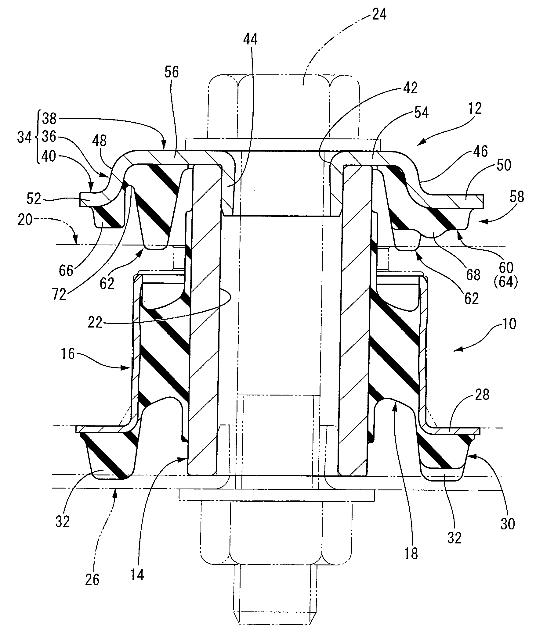
[0039]Referring first to an axial cross section of FIG. 1, there is schematically shown a cylindrical elastic mount assembly connecting a vehicle differential carrier and a vehicle body in a vibration damping fashion which is constructed according to one embodiment of the present invention. As obvious in FIG. 1, the cylindrical elastic mount assembly according to the present embodiment includes a cylindrical elastic mount in the form of a differential mount 10 and a stopper for a cylindrical elastic mount in the form of a discrete stopper 12 assembled to the differential mount 10.

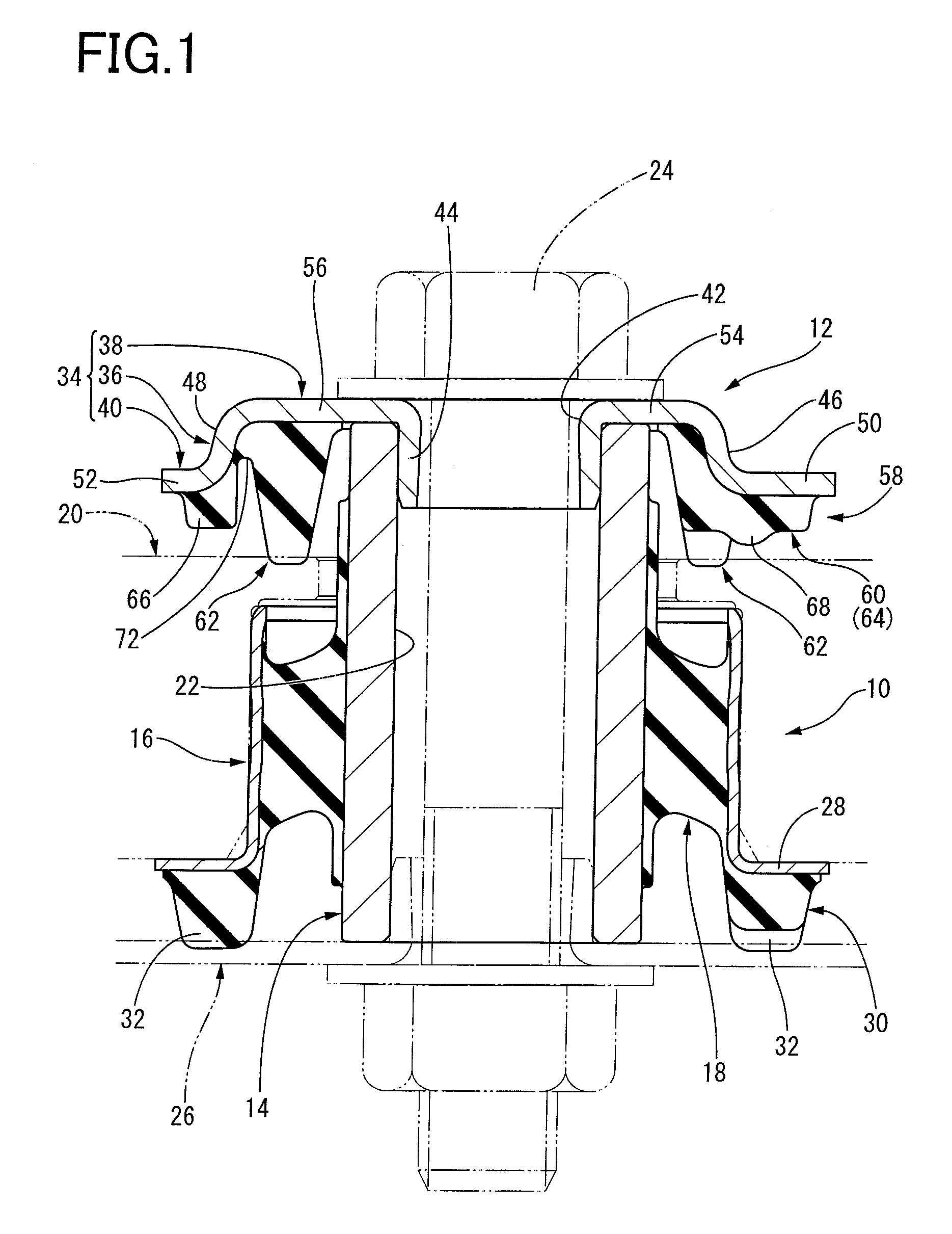
[0040]The differential mount 10 constituting the cylindrical elastic mount according to the present embodiment has a known structure, as obvious in each of FIGS. 1 and 2, in which a shaft member in the form of an inner sleeve 14 and an outer cylindrical member in the ...


PUM


Abstract

A stopper for a cylindrical elastic mount includes a concave portion which is formed at each of a plurality of locations on a circumference of a cylindrical portion of a stopper fitting, the concave portion being concaved in a radially inward direction to partially enlarge a width of an outward flange so as to provide a large width portion on an enlarged width portion of the outward flange of a first rubber portion. The stopper further includes a plurality of second rubber portions each of which is fixedly disposed only between adjacent concave portions in a circumferential direction of a bottom portion and protruding higher than the first rubber portion. The first and each of the plurality of the second rubber portions are separated by a groove-shaped gap that is provided so as to continuously extend around each of the plurality of second rubber portions.

Description

[0001]The present application is based on Japanese Patent Application No. 2006-267369 filed on Sep. 29, 2006, the contents of which are incorporated herein by reference.BACKGROUND OF THE INVENTION[0002]1. Field of the Invention[0003]The present invention relates to a stopper for a cylindrical elastic mount and a cylindrical elastic mount assembly, in particular to a stopper for cylindrical elastic mount that is suitably used as a discrete stopper assembled to a cylindrical elastic mount such as a differential mount, a member mount or a body mount for an automobile, as well as a cylindrical elastic mount constructed by assembling such stopper.[0004]2. Discussion of Related Art[0005]As a type of an elastic mount interposed between two members to connect these two members, a first member and a second member constituting a vibration transmission system, there is known a cylindrical elastic mount which includes a predetermined shaft member, an outer cylindrical member disposed radially o...

Claims


Application Information

Patent Timeline
Patent Type & Authority Applications(United States)
IPC IPC(8): F16F7/12
CPCF16F1/3828F16C27/02
Inventor HAYASHI, TAKASHISASAKI, KUNIO
Owner SUMITOMO RIKO CO LTD
Why Eureka
Try Eureka