Integrated Acceleration Data Structure for Physics and Ray Tracing Workload

a workload and acceleration data technology, applied in the field of computer processing, can solve the problems of rasterization suffering from some drawbacks, modern monitors display images, and use relatively low amounts of computational power

Inactive Publication Date: 2008-04-03
IBM CORP
View PDF2 Cites 30 Cited by
  • Summary
  • Abstract
  • Description
  • Claims
  • Application Information

AI Technical Summary

Problems solved by technology

One limitation of rendering realistic images is that modern monitors display images through the use of pixels.
Rasterization is effective at rendering graphics quickly and using relatively low amounts of computational power; however, rasterization suffers from some drawbacks.
For example, rasterization often suffers from a lack of realism because it is not based on the physical properties of light, rather rasterization is based on the shape of three-dimensional geometric objects in a scene projected onto a two dimensional plane.
Furthermore, the computational power required to render a scene with rasterization scales directly with an increase in the complexity of the scene to be rendered.
As image processing becomes more realistic, rendered scenes also become more complex.
Therefore, rasterization suffers as image processing evolves, because rasterization scales directly with complexity.
Furthermore, ray tracing also handles increases in scene complexity better than rasterization as scenes become more complex.
This is due to the fact that the same number of rays may be cast into a scene, even if the scene becomes more complex.
One major drawback of ray tracing is the large number of calculations, and thus processing power, required to render scenes.
This leads to problems when fast rendering is needed.
Due to the increased computational requirements for ray tracing it is difficult to render animation quickly enough to seem realistic (realistic animation is approximately twenty to twenty-four frames per second).

Method used


Image

  • Integrated Acceleration Data Structure for Physics and Ray Tracing Workload
  • Integrated Acceleration Data Structure for Physics and Ray Tracing Workload
  • Integrated Acceleration Data Structure for Physics and Ray Tracing Workload

Examples


Embodiment Construction

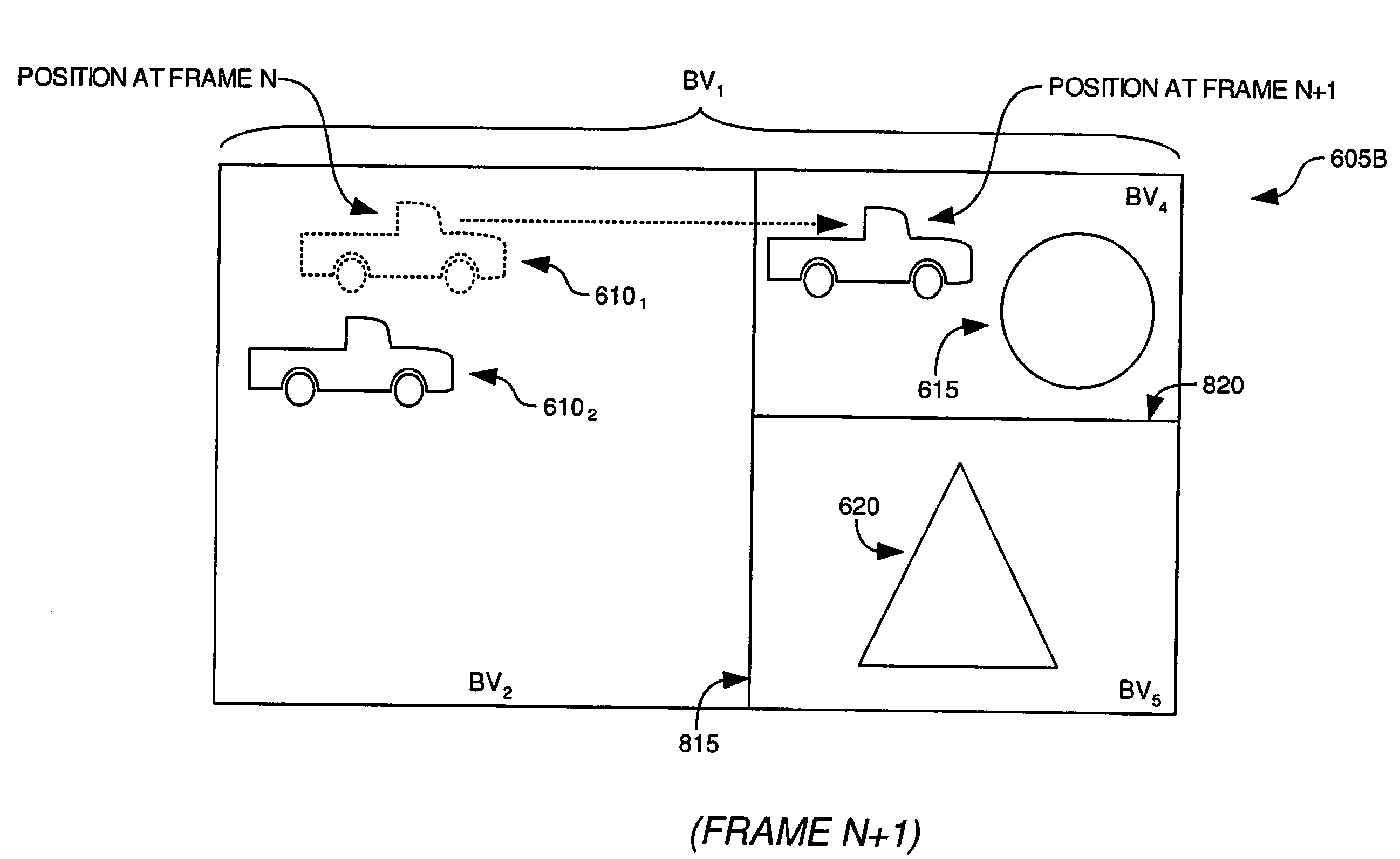
[0026]Embodiments of the invention provide an integrated acceleration data structure which may be used by a physics engine and an image processing system. According to one embodiment of the invention, an integrated acceleration data structure may be formed by creating an initial or upper portion representing a spatially oriented hierarchy of bounding volumes which partition a three dimensional scene, and a second or lower portion representing objects located within the three dimensional scene. The upper portion of the integrated acceleration data structure may be connected to the lower portion of the integrated acceleration data structure by branches from nodes defining bounding volumes within the three dimensional scene, wherein the bounding volumes encompass objects located within the three dimensional scene. According to embodiments of the invention, by creating an integrated acceleration data structure, only one data structure may be necessary for a physics engine to perform cal...


PUM


Abstract

According to embodiments of the invention, a data structure may be created which may be used by both an image processing system and by a physics engine. The data structure may have an initial or upper portion representing bounding volumes which partition a three dimensional scene and a second or lower portion representing objects within the three dimensional scene. The integrated acceleration data structure may be used by an image processing system to render a two dimensional image from a three dimensional scene, and by a physics engine to perform physics based calculations in order to simulate physical phenomena in the three dimensional scene. Furthermore, the physics engine may update the integrated acceleration data structure in response to changes in position or shape of objects due to physical phenomena.

Description

BACKGROUND OF THE INVENTION[0001]1. Field of the Invention[0002]Embodiments of the invention generally relate to the field of computer processing.[0003]2. Description of the Related Art[0004]The process of rendering two-dimensional images from three-dimensional scenes is commonly referred to as image processing. As the modern computer industry evolves image processing evolves as well. One particular goal in the evolution of image processing is to make two-dimensional simulations or renditions of three-dimensional scenes as realistic as possible. One limitation of rendering realistic images is that modern monitors display images through the use of pixels.[0005]A pixel is the smallest area of space which can be illuminated on a monitor. Most modern computer monitors will use a combination of hundreds of thousands or millions of pixels to compose the entire display or rendered scene. The individual pixels are arranged in a grid pattern and collectively cover the entire viewing area of ...

Claims


Application Information

Patent Timeline
Patent Type & Authority Applications(United States)
IPC IPC(8): G06T13/00
CPCG06T15/005G06T15/40G06T15/06
Inventor SHEARER, ROBERT A.
Owner IBM CORP
Why Eureka
Try Eureka