Illuminating device

a technology of illumination device and pedestrian, which is applied in the direction of lighting and heating apparatus, light source combination, and footway, etc., can solve the problems of late coping of the driver with respect to flying out of the pedestrian, difficult for the driver of the automobile to visualize the pedestrian, etc., and achieve the effect of easy visualization of the pedestrian

Active Publication Date: 2008-04-03
STANLEY ELECTRIC CO LTD
View PDF4 Cites 45 Cited by
  • Summary
  • Abstract
  • Description
  • Claims
  • Application Information

AI Technical Summary

Benefits of technology

[0006]An object of the present invention is to provide an illuminating device in which the driver of the automobile can easily visualize the pedestrian, etc. on the footway.

Problems solved by technology

However, in the former illuminating device, there is a case difficult for the driver of the automobile to visualize a pedestrian, etc. on the footway even when light of appropriate illuminance is illuminated to the footway.
When it is late that the driver of the automobile finds the pedestrian, etc. on the footway, there is also a fear that coping of the driver with respect to flying-out of the pedestrian, etc. to the roadway is late.

Method used


Image

  • Illuminating device
  • Illuminating device
  • Illuminating device

Examples


first embodiment

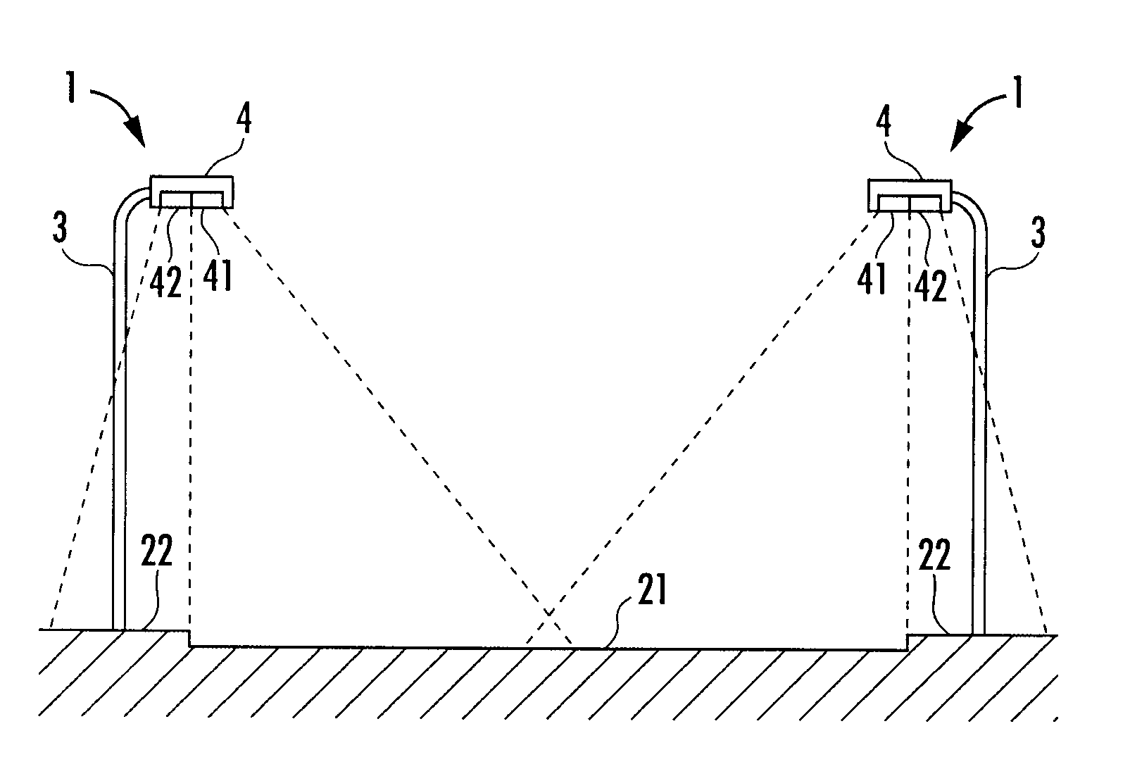
[0033]As shown in FIG. 1, an illuminating device 1 of the present invention is arranged in a street 2 having a roadway 21 and a footway 22. The illuminating device 1 is constructed by a support portion 3 extending from the footway 22 in a vertical direction, and an illuminating main body 4 arranged at an upper end of the support portion 3. The illuminating main body 4 has a roadway side light source portion 41 for irradiating light to the roadway 21, and a footway side light source portion 42 for irradiating light to the footway 22.

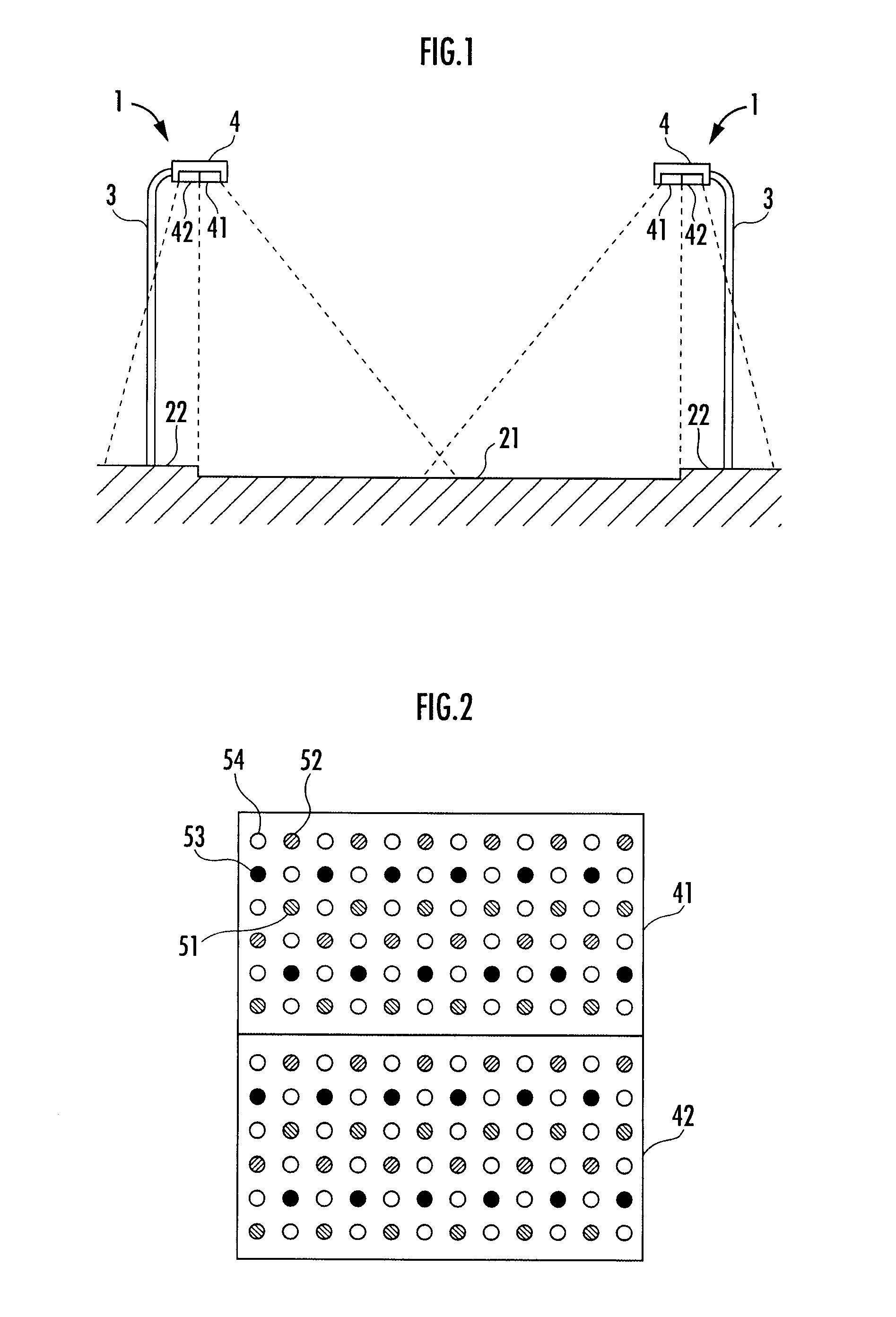
[0034]As shown in FIG. 2, each of light sources of both the light source portions 41, 42 is constructed by arraying plural LEDs 51 to 54 of the four colors of red, green, blue and yellow (or white) colors. The respective LEDs 51 to 54 are dispersively arranged in preferable balance in both the light source portions 41, 42 such that a ratio of red LED 51, green LED 52, blue LED 53 and yellow (white) LED 54 becomes a ratio of 1:1:1:3.

[0035]Further, the illu...

third embodiment

[0053]As a third embodiment, a light source of white light of 5800 K in color temperature may be also used as the light source of the footway side light source portion 42, and a light source of white light of 3800 K in color temperature may be also used as the light source of the roadway side light source portion 41. FIG. 8 shows spectral distributions in this case. In FIG. 8, P shows a spectral distribution of the light source of the footway side light source portion 42, and C shows a spectral distribution of the light source of the roadway side light source portion 41.

[0054]In the first embodiment, the spectral characteristics of light irradiated from the footway side light source portion 42 are explained so as to adjust the output of each of the LEDs 51 to 54 by the above output adjusting means such that the value IP obtained by the above formula (2) is larger than the value IC obtained by the formula (2) of the spectral characteristics of light irradiated from the roadway side l...

fourth embodiment

[0055]As shown as a fourth embodiment in FIG. 9, two separate illuminating main bodies 4′, 4″ may be also arranged in the support portion 3 of the illuminating device 1, and the roadway side light source portion 41 may be also arranged in the illuminating main body 4′, and the footway side light source portion 42 may be also arranged in the illuminating main body 4″.


PUM


Abstract

An illuminating device able to easily visualize a pedestrian, etc. on a footway by the driver of an automobile is provided. The illuminating device has a footway side light source portion for irradiating light of spectral characteristics rich in blue-green color light to the footway, and a roadway side light source portion for irradiating light of spectral characteristics rich in green-red color light to a roadway. Further, the spectral characteristics of the light irradiated from the footway side light source portion are set such that a value Ip obtained by the following formula (1) is greater than a value IC obtained by the following formula (1) from the spectral characteristics of the light irradiated from the roadway side light source portion.
I=abS(λ)·V(λ)λ380780S(λ)·V(λ)λ(1)

Description

BACKGROUND OF THE INVENTION[0001]1. Field of the Invention[0002]The present invention relates to an illuminating device arranged in a street having a roadway and a footway and illuminating the roadway and the footway.[0003]2. Background Art[0004]An illuminating device for an intersecting point is formerly known as the illuminating device for illuminating the street (e.g., see Japanese Patent Laid-Open No. 2005-158540). This illuminating device has a light source and a reflecting mirror of a special shape arranged in an upper portion of the light source. The reflecting mirror is constructed so as to project irradiation light for directing light of the light source to a central portion of the intersecting point, irradiation light for directing this light onto a close pedestrian crossing, and irradiation light for illuminating a rear area. Thus, illuminance deficiency near the center of the intersecting point, a pedestrian crossing portion and a crossing standby portion of the footway ...

Claims


Application Information

Patent Timeline
Patent Type & Authority Applications(United States)
IPC IPC(8): F21V9/08H01L33/48
CPCF21S2/00F21S8/086F21V9/08F21Y2113/005F21W2131/103F21Y2101/02F21Y2105/001F21W2111/02F21Y2101/00F21Y2105/10F21Y2115/10F21Y2113/13
Inventor KITA, YASUSHIKOJIMA, SHINICHIMINODA, TAKAKOTAKENOBU, NAOKO
Owner STANLEY ELECTRIC CO LTD
Why Eureka
Try Eureka