Eureka AIR delivers breakthrough ideas for toughest innovation challenges, trusted by R&D personnel around the world.

Optical pickup unit capable of preventing a laser diode from destroying from static electricity

a pickup unit and static electricity technology, applied in the field of optical pickup units, can solve the problems of blue laser diodes being destroyed, blue laser diodes being very expensive, and large-scale, and achieve the effect of preventing the destruction of blue laser diodes

Inactive Publication Date: 2008-04-03
MITSUMI ELECTRIC CO LTD
View PDF1 Cites 10 Cited by
  • Summary
  • Abstract
  • Description
  • Claims
  • Application Information

AI Technical Summary

Benefits of technology

The present invention provides an optical pickup unit that prevents damage to the laser diode from static electricity. The optical pickup unit includes a short-land printed board that short-circuits between the laser diode and the ground terminal using solder. The optical pickup unit also includes reinforcing plates to strengthen the connection between the laser diode and the flexible printed boards. Additionally, the optical pickup unit may include a side cover for protection and a three-wavelength holding optical pickup unit that can record or play optical recoding media using different laser beams.

Problems solved by technology

However, if the first laser diode and the second laser diode are formed as separate parts, it is inconvenient that the two-wavelength handling optical pickup unit comprises a lot of parts and is large-scale.
Incidentally, the blue laser diode is very expensive and has the property of extreme static-sensitive.
Therefore, there is a problem where the blue laser diode is destroyed caused by static electricity.
However, such a handling method is disadvantageous in that it can have a detrimental effect on the blue laser diode because heat transfers to the LD terminal of the blue laser diode on applying or melting the solder.
In addition, inasmuch as the LD terminal of the blue laser diode is put into an external exposed state after the blue laser diode is mounted on the outer wall of the optical base, it is feared that a person (a worker) is directly in contact with the LD terminal of the blue laser diode on dealing with the optical pickup unit.
As a result, there is a possibility that the blue laser diode destroys because of effect of static electricity accumulated in the person (the worker).

Method used


Image

  • Optical pickup unit capable of preventing a laser diode from destroying from static electricity
  • Optical pickup unit capable of preventing a laser diode from destroying from static electricity
  • Optical pickup unit capable of preventing a laser diode from destroying from static electricity

Examples


Embodiment Construction

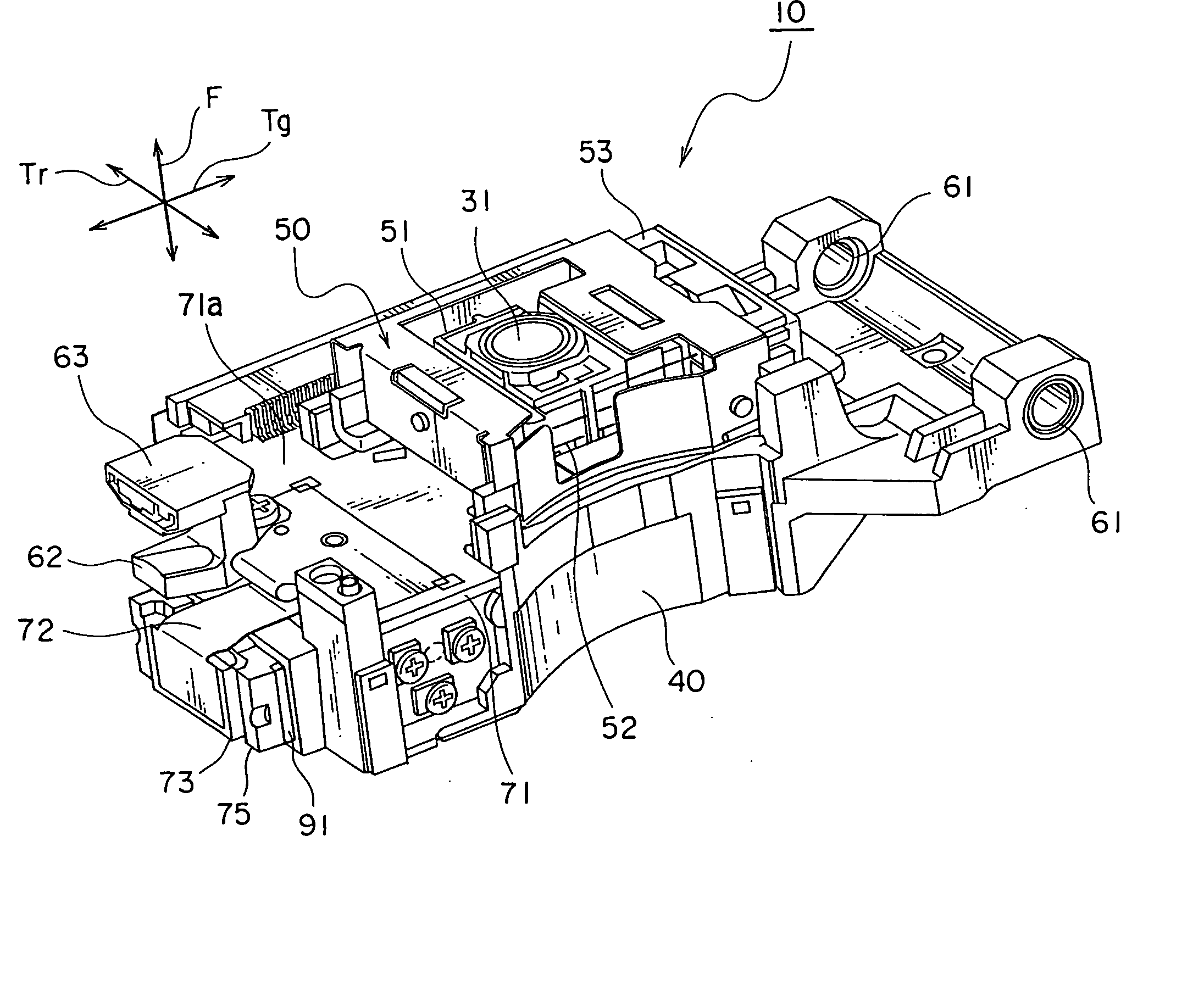
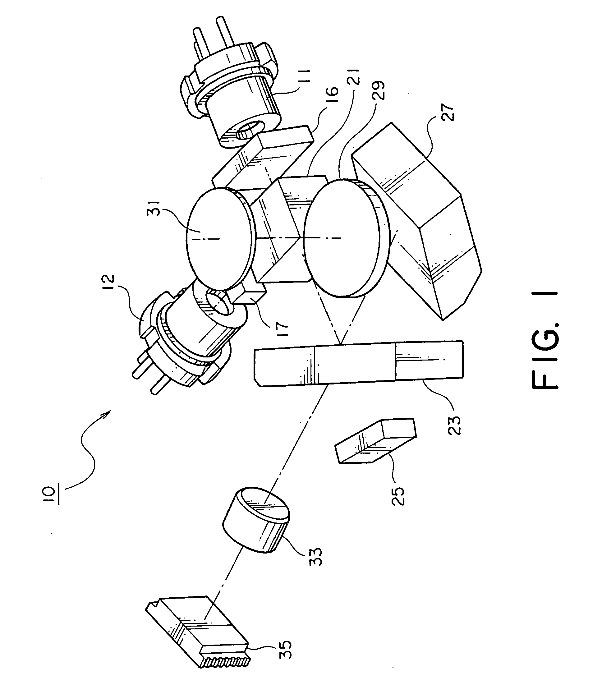
[0033] In the manner which is described above, in optical disc drives, it has been developed one in which a special optical pickup unit is mounted in order to enable to record / reproduce data in / from not only the DVD and the CD but also a high definition DVD (HD-DVD). The special optical pickup unit of the type is for carrying out recording or reproducing by selectively using three kinds of laser beams, namely, a laser beam having a middle wavelength (a wavelength band of 650 nm) for the DVD, a laser beam having a long wavelength (a wavelength band of 780 nm) for the CD, and a laser beam having a short wavelength (a wavelength band of 410 nm) for the HD-DVD. The special optical pickup unit is called a three-wavelength handling optical pickup unit.

[0034]FIG. 1 is a system configuration view of an optical system of the three-wavelength handling optical pickup unit depicted at 10 according to an embodiment of this invention. The illustrated three-wavelength handling optical pickup unit...


PUM

PropertyMeasurementUnit
wavelength bandaaaaaaaaaa
distanceaaaaaaaaaa

Abstract

An optical pickup unit includes an optical base and at least one laser diode mounted on an outer wall of the optical base. The laser diode has a base portion, and an LD terminal and a GND terminal which extend from the base portion to a rear surface side. Formed on a short-land flexible printed board, conductive patterns enable to short-circuit the LD terminal and the GND terminal of the laser diode at a position apart from the LD terminal.

Description

[0001] This application is based upon and claims the benefit of priority from Japanese patent application JP 2006-270321, filed on Oct. 2, 2006, the disclosure of which is incorporated herein in its entirety by reference. BACKGROUND OF THE INVENTION [0002] This invention relates to an optical pickup unit and, in particular, to a three-wavelength holding optical pickup unit which is enable to carry out recording or reproducing for three kinds of optical discs by selectively using three kinds of laser beams having different wavelengths. [0003] As well know in the art, an optical disc drive is a device for reading / writing information from / into an optical disc (CD, CD-ROM, CD-R / RW, DVD-ROM, DVD±R / RW, Blu-ray disc, HD-DVD, or the like). In order to achieve reading / writing the information from / into the optical disc, the optical disc drive of this type comprises an optical pickup unit for irradiating a laser beam onto the optical disc and for detecting its reflected beam. [0004] In the man...

Claims


Application Information

Patent Timeline
Patent Type & Authority Applications(United States)
IPC IPC(8): G11B7/002
CPCG11B7/127G11B2007/0006G11B7/131G11B7/1275G11B7/126
Inventor NISHIYAMA, TAKAHIKOMIURA, HIDEKI
Owner MITSUMI ELECTRIC CO LTD
Why Eureka
Eureka Blog
Learn More