Localization apparatus for recognizing location of node in sensor network and method thereof

a sensor network and localization apparatus technology, applied in the field of localization apparatus for recognizing the location of nodes in the sensor network, can solve the problems of difficult to secure the line of sight (los), impossible to accurately measure the distance, and inability to obtain accurate distance measurement, etc., to achieve the effect of accurately detecting the location of nodes

Inactive Publication Date: 2008-04-03
ELECTRONICS & TELECOMM RES INST
View PDF12 Cites 83 Cited by
  • Summary
  • Abstract
  • Description
  • Claims
  • Application Information

AI Technical Summary

Benefits of technology

[0011]An embodiment of the present invention is directed to providing a localization apparatus for accurately detecting a location of a node selectively using neighbor nodes having less obstacle factors in a sensor network, and a method thereof.
[0012]Another embodiment of the present invention is directed to providing a localization apparatus for accurately obtaining the location information of a target node with a less number of reference nodes by selectively using reference nodes having less obstacle factors, and a method thereof.

Problems solved by technology

In case of the ToA method, it is impossible to accurately measure a distance if a signal has a fast propagation speed like a radio frequency (RF) signal.
In addition, it is impossible to obtain accurate distance measuring results if signals having a low propagation speed, such as an ultrasonic wave or a sound wave, are used.
That is, it is difficult to secure line of sight (LoS) if an ultrasonic wave or a sound wave is used.
Therefore, it is impossible to accurately measure a distance between two nodes due to the influence of obstacles.
However, the RSS method has a disadvantage of low accuracy compared to other distance measuring methods.
Particularly, the measuring result of the RSS method is significantly influenced by obstacles that reflect or absorb the RF signal.
Such methods were developed because the localization method using distance information may diffuse an error in a sensor network having multi-hop.
However, it is very difficult to satisfy such conditions in a real environment of a sensor network, such as a general indoor place.
Therefore, the large amount of computation is required to accurately detect the location.

Method used


Image

  • Localization apparatus for recognizing location of node in sensor network and method thereof
  • Localization apparatus for recognizing location of node in sensor network and method thereof
  • Localization apparatus for recognizing location of node in sensor network and method thereof

Examples


Embodiment Construction

[0027]The advantages, features and aspects of the invention will become apparent from the following description of the embodiments with reference to the accompanying drawings, which is set forth hereinafter. In addition, if it is considered that detailed description on a related art may obscure the points of the present invention, the detailed description will not be provided herein. The preferred embodiments of the present invention will be described in detail hereinafter with reference to the attached drawings.

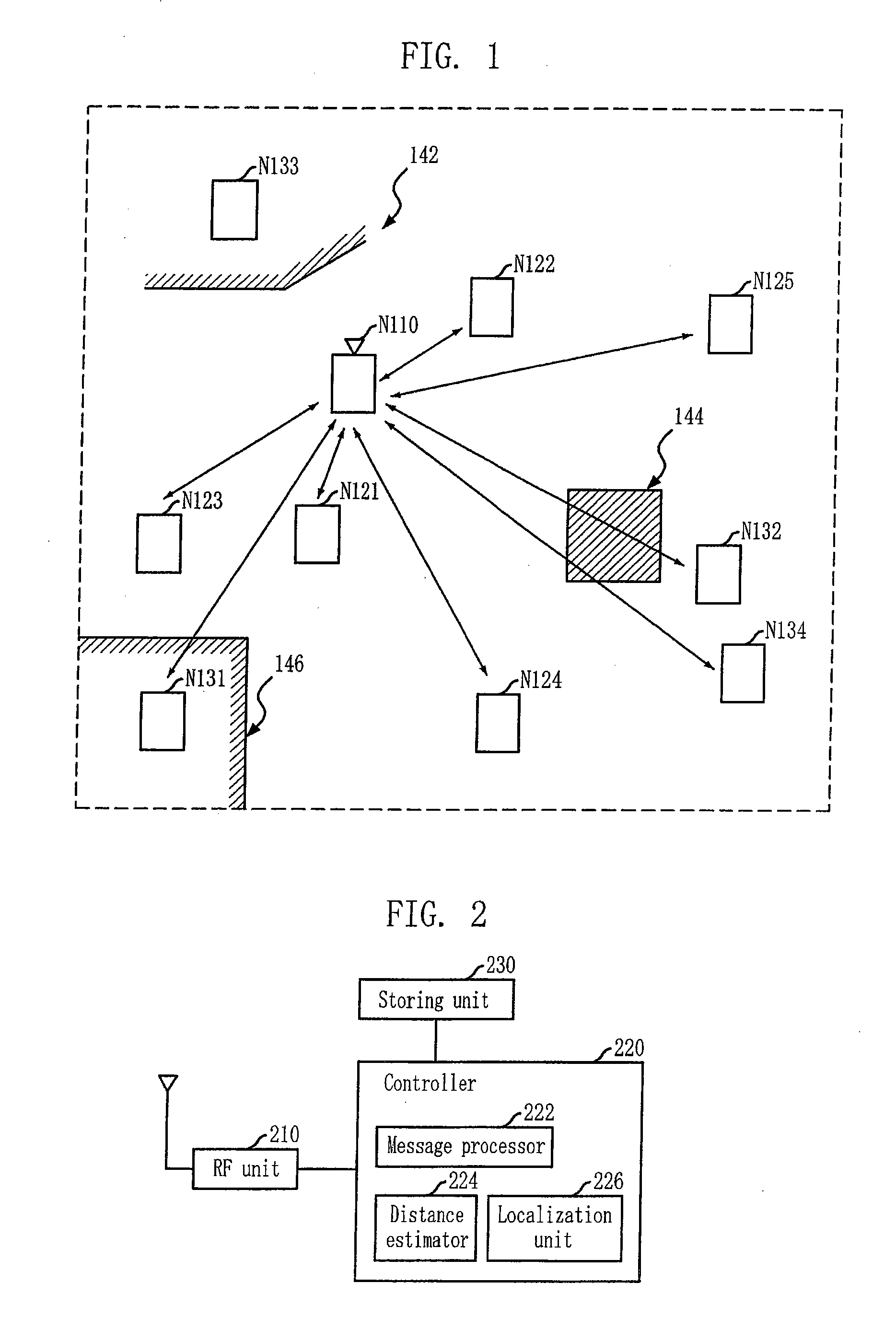
[0028]FIG. 1 is a diagram illustrating a sensor network where an embodiment of the present invention is applied.

[0029]As shown in FIG. 1, the sensor network includes a target node N110 and anchor nodes N121 to N125 and N131 to N134. The target node N110 is a node to obtain the location information thereof, and each of the anchor nodes has own location information. Neighbor nodes are anchor nodes located within the communication range of the target node N110 having no locatio...


PUM


Abstract

Provided are a localization apparatus for recognizing a location of a node in a sensor network and a method thereof. The method includes the steps of: a) selecting reference nodes from a plurality of anchor nodes to be used for triangulation; and b) obtaining location information of a target node by performing triangulation using the selected reference node, wherein in the step a), the reference nodes are selected by removing anchor nodes having obstacle factor from a plurality of the anchor nodes where the obstacle factor causes error in a distance measured by the target node.

Description

CROSS-REFERENCE(S) TO RELATED APPLICATIONS[0001]The present invention claims priority of Korean Patent Application No. 10-2006-0095567, filed on Sep. 29, 2006, which is incorporated herein by reference.BACKGROUND OF THE INVENTION[0002]1. Field of the Invention[0003]The present invention relates to a localization apparatus for recognizing a location of a node in a sensor network and a method thereof; and, more particularly, to a localization apparatus selectively using neighbor nodes having less obstacle factors and a method thereof.[0004]2. Description of Related Art[0005]Triangulation has been generally used to detect a location of a node in a wireless sensor network. The triangulation uses coordinates and distances of more than three anchor nodes to detect the location of a node. A localization method using triangulation is generally classified into a localization method using information about measured distances and a localization method not using information about measured dista...

Claims


Application Information

Patent Timeline
Patent Type & Authority Applications(United States)
IPC IPC(8): H04Q7/24H04W64/00H04W84/18
CPCH04W84/18H04W64/00G01S5/0027
Inventor PARK, JONG-JUNLEE, JONG-OHKIM, SUN-JOONGPYO, CHEOL-SIGCHAE, JONG-SUK
Owner ELECTRONICS & TELECOMM RES INST
Why Eureka
Try Eureka