
Solid-state laser gain module

a laser gain module and solid-state technology, applied in the direction of laser details, optical resonator shape and construction, electrical equipment, etc., can solve the problems of high cost of space-based laser systems, large complex laser systems employed, and many systems employing nd:yag as laser gain materials achieve optical efficiencies of only 1-2%

Inactive Publication Date: 2008-04-03
NASA
View PDF2 Cites 11 Cited by
  • Summary
  • Abstract
  • Description
  • Claims
  • Application Information

AI Technical Summary

Benefits of technology

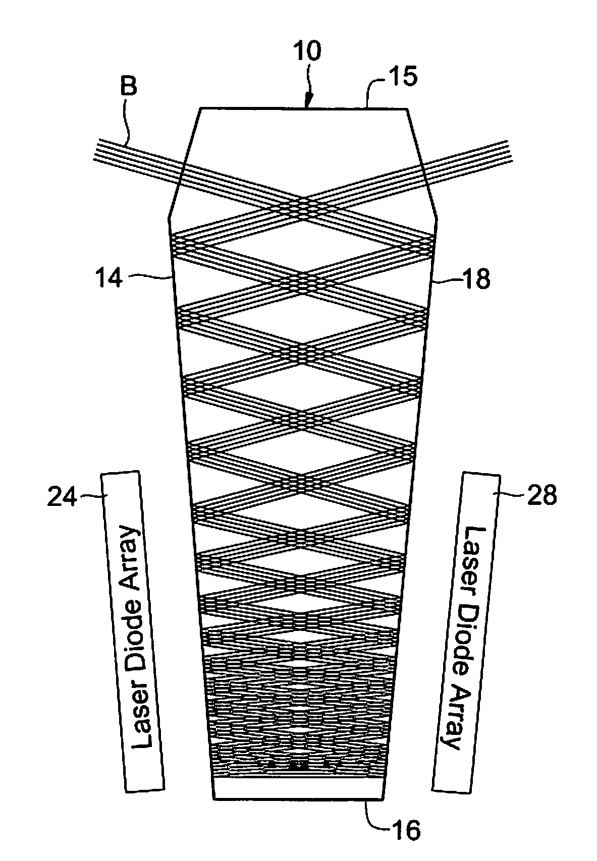
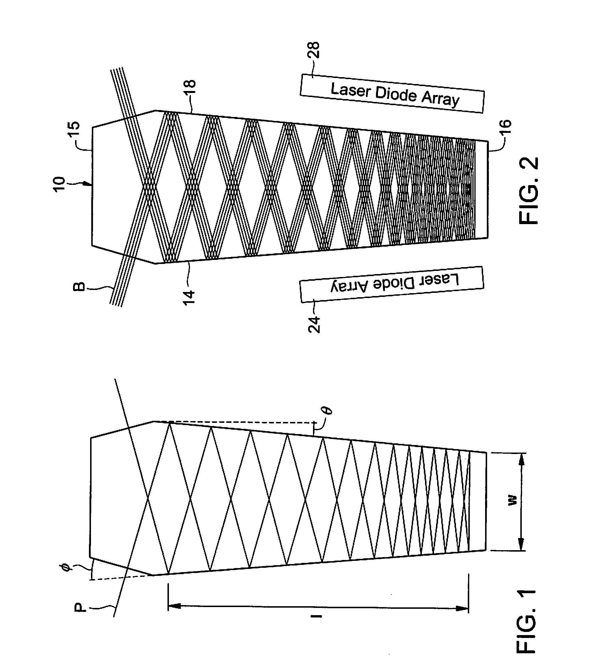
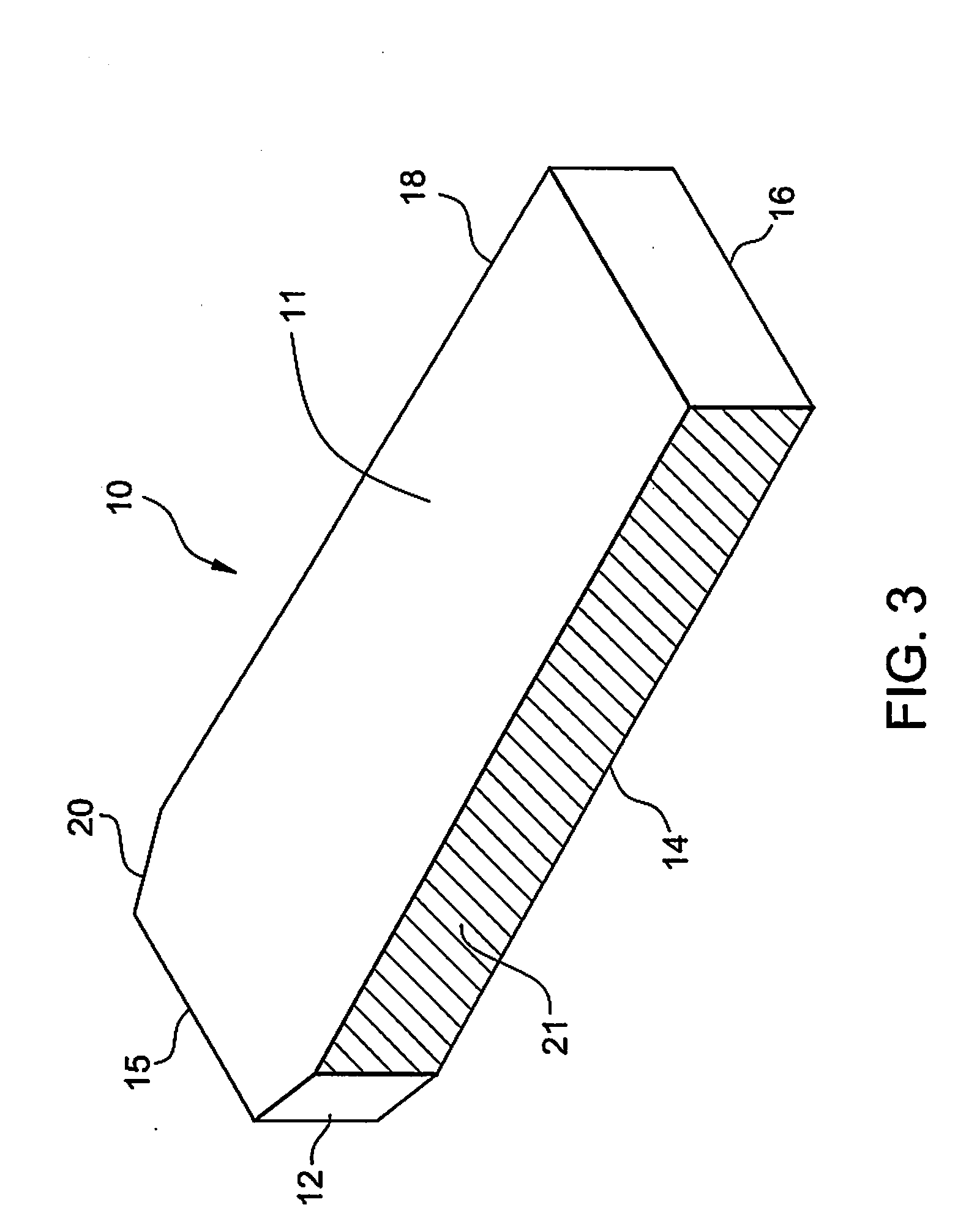
[0008]In another embodiment, the invention may be characterized as a laser system that comprises a laser gain module that includes a “spoiled” hexagonal shaped slab wherein two opposing non-parallel sides of the slab are elongated in comparison to the remaining four sides. (A “spoiled” hexagon describes a hexagon with 3 pairs of equal faces, yet each face is a different length than either adjacent face.) The elongated sides of the slab are also tapered so as to create an angle of approximately 1 degree along the elongated sides. The system may also include up to four laser diode arrays, possibly more for very high power systems, so as to provide additional power to the laser gain module. The additional power provided to the laser gain module may result in greater amplification of the laser beam as it propagates through the laser gain module.

Problems solved by technology

Achieving the maximum laser energy from the smallest possible laser system is an ongoing challenge in the design of laser systems.
Large complicated laser systems have been employed to achieve the desired laser gain and efficiencies.
However, many of the systems employing Nd:YAG as a laser gain material achieve optical efficiencies of only 1-2%.
The harsh environment and high cost of space based laser systems demand that every effort be made to achieve maximum efficiencies from these systems.
The smallest efficiency gain may result in extensive mass and size reduction that translate into extensive cost savings in a spacecraft.
Thus, those skilled in the art expend great effort to increase efficiencies of such laser systems.

Method used


Image

  • Solid-state laser gain module
  • Solid-state laser gain module
  • Solid-state laser gain module

Examples


Embodiment Construction

[0015]In the following detailed description, reference is made to the accompanying drawings that form a part hereof, and in which are shown, by way of illustration, specific embodiments, which may be practiced. These embodiments are described in sufficient detail to enable those skilled in the art to practice the embodiments. Those skilled in the art will readily understand that other embodiments may be utilized, and that logical, mechanical, electrical and other changes may be made, without departing from the scope of the embodiments. Ranges of parameter values described herein are understood to include all sub-ranges falling therewithin. The following detailed description may, therefore, not to be taken in a limiting sense but as illustrative of the embodiments of the present invention.

[0016]FIG. 1 shows a laser gain module 10 that includes a spoiled hexagonal or coffin shape. The laser gain module 10 may be of a crystal such as neodymium yttrium aluminum garnet (Nd:YAG) which emi...


PUM


Abstract

A laser gain module comprises a spoiled hexagonal shaped slab for receiving a laser beam. The laser beam enters the slab on one face and is reflected internally at one or more faces. The laser beam propagates through the slab and may be amplified with each reflection. The laser gain module also comprises two opposing non-parallel sides that are elongated in comparison to the remaining four sides thus creating the spoiled hexagon geometry. The module may also include two or four laser diode arrays positioned so as to constitute a side pumping arrangement to provide additional energy to the laser gain module. The additional energy provided to the laser gain module may result in greater amplification of the laser beam as it propagates through the laser gain module.

Description

ORIGIN OF THE INVENTION[0001]The invention described herein was made by an employee of the United States Government, and may be manufactured and used by or for the Government for governmental purposes without the payment of any royalties thereon or therefor.FIELD OF THE INVENTION[0002]The present invention relates generally to optical amplifiers, and in particular to a diode pumped neodymium yttrium aluminum garnet (Nd:YAG) solid-state slab laser gain module.BACKGROUND[0003]Achieving the maximum laser energy from the smallest possible laser system is an ongoing challenge in the design of laser systems. Large complicated laser systems have been employed to achieve the desired laser gain and efficiencies. Elaborate and often complex laser reflecting schemes and different laser gain media are often used in the effort to achieve greater laser system efficiency. One type of laser gain medium used by those skilled in the art includes the solid-state laser medium. Laser amplifiers operate ...

Claims


Application Information

Patent Timeline
IPC IPC(8): H01S3/08
CPCH01S3/0606H01S3/0625H01S3/2333H01S3/1611H01S3/1643H01S3/0941
Inventor COYLE, DONALD B.
Owner NASA
Learn More