
Multiband mixer

a multi-band mixer and mixer technology, applied in the field of frequency conversion devices, can solve the problems of increasing the size of the silicon area required for rf hardware, increasing both and achieving the effect of increasing the size of the silicon area required, increasing the cost and the size of a dual-band mobile phon

Inactive Publication Date: 2008-01-29
NOKIA TECHNOLOGLES OY
View PDF10 Cites 5 Cited by
  • Summary
  • Abstract
  • Description
  • Claims
  • Application Information

AI Technical Summary

Benefits of technology

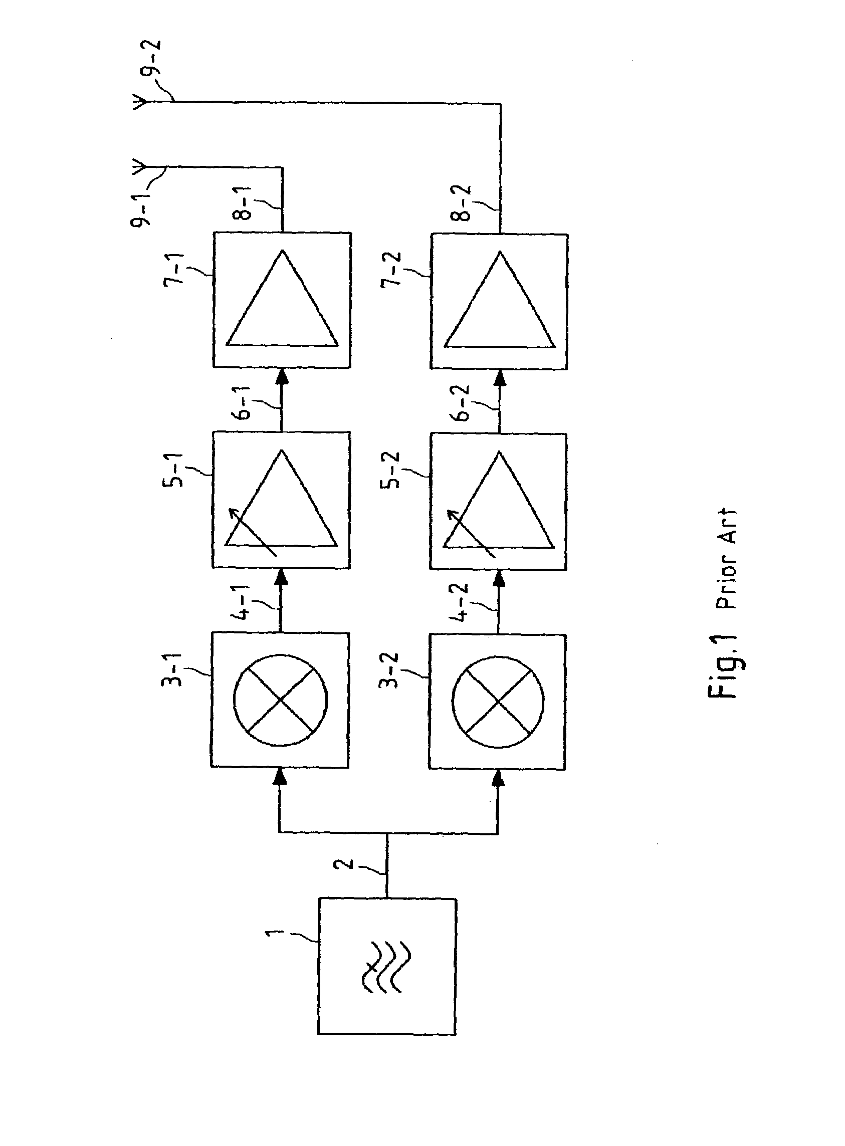
[0006]In prior art dual-band mobile phones, two mixers 3-1 and 3-2 are provided, so that the filtered I / Q-modulated base-band signal 2 can be transferred to both the GSM900 and GMS1800 bands. Providing two mixers increases the size of the silicon area required for the RF hardware and thus increases both the costs and the size of a dual-band mobile phone.
[0007]Motivated by these disadvantages encountered in the RF hardware of prior art dual-band mobile phones, it is thus the object of the invention to provide a more efficient device and method for frequency conversion of a signal from a source frequency band to a sub-band of at least two different target frequency bands.
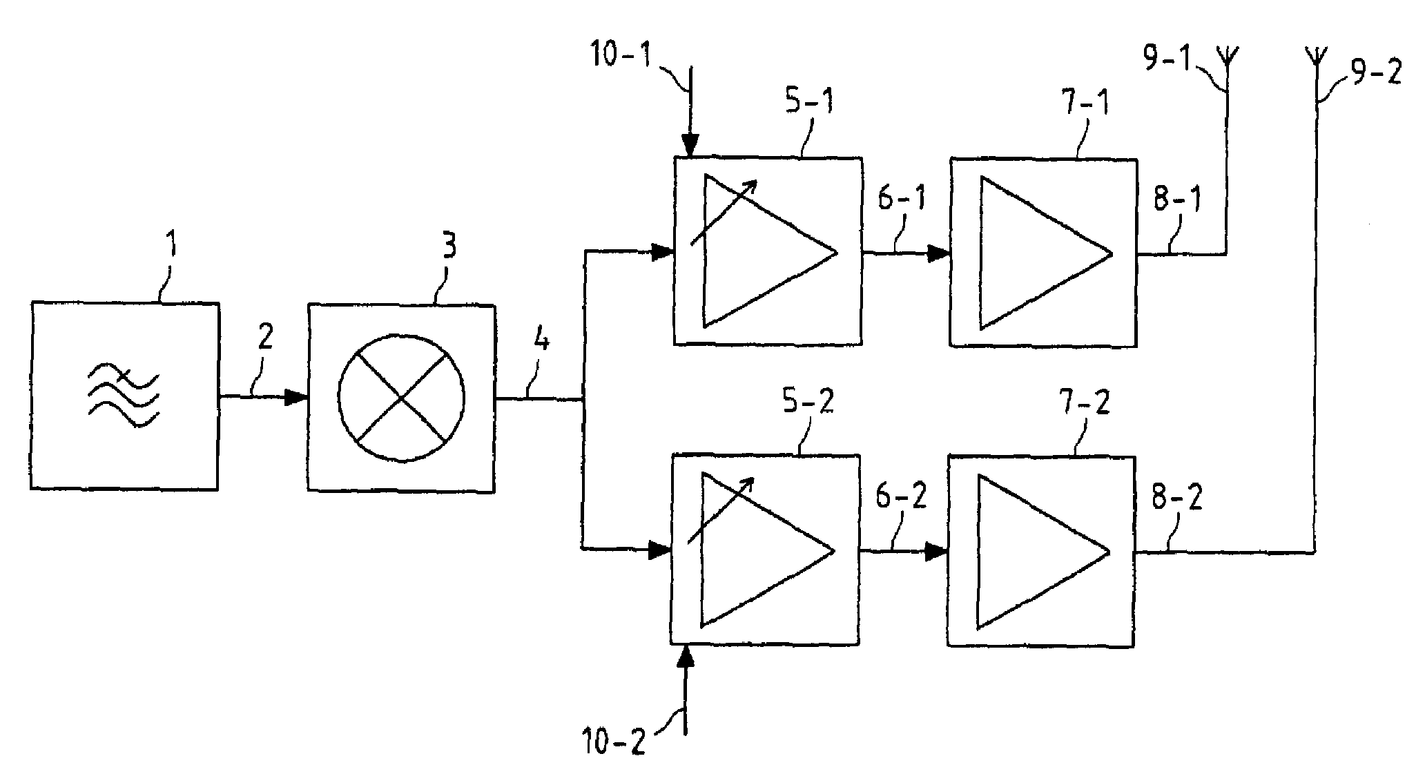
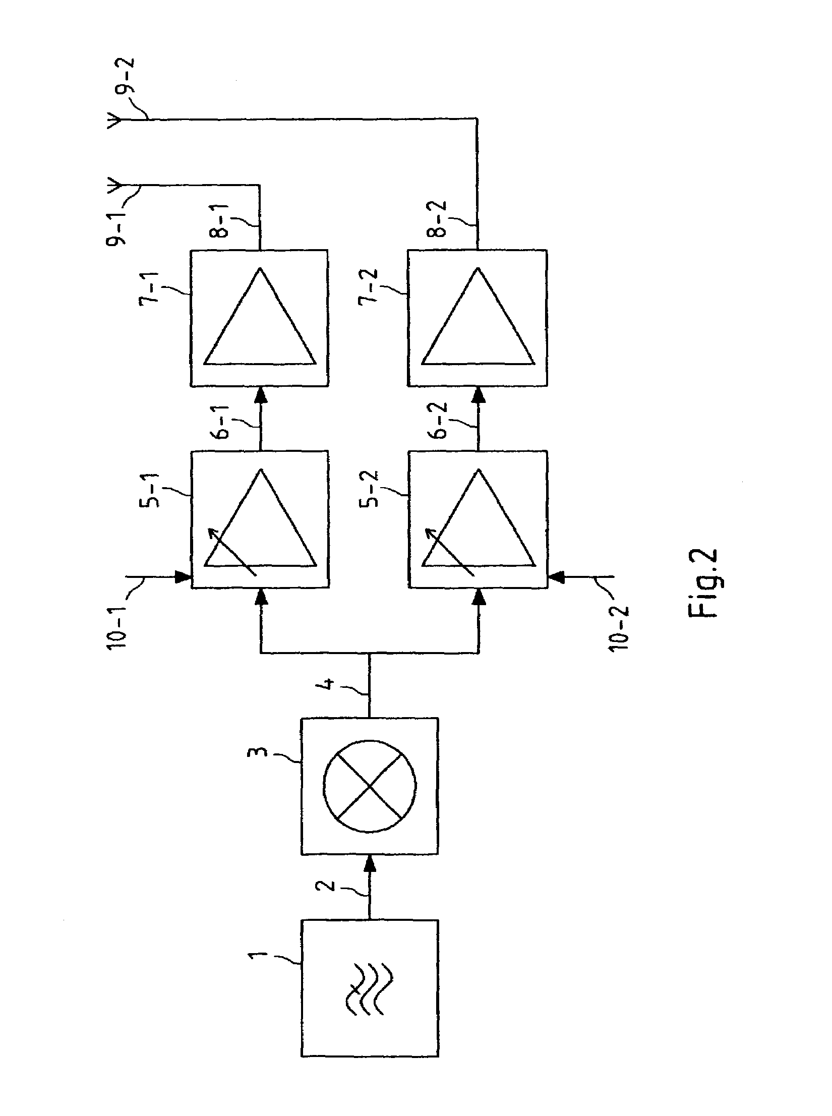
[0009]The multi-band mixer according to the present invention is able to transfer the signal that is applied to its input to one target frequency sub-band at a time, where said target frequency sub-band is located in one of at least first and second target frequency bands. The signal does not necessarily have to be a base-band signal, and also the transfer of a signal from an intermediate frequency band to a target sub-band in one of at least first and second RF frequency bands is possible. The signal that has been transferred to a target frequency sub-band in one of at least a first and second target frequency band by the multi-band mixer is output from the signal output of the multi-band mixer and subsequently input to all switchable VGAs in said bank of switchable VGAs. Each of said switchable VGAs is frequency-dependent and may for instance be optimized for the center frequency of exactly one of said at least first and second target frequency bands, so that for all target frequency sub-bands that lie within one of said target frequency bands, optimum amplification or a reduced noise contribution is achieved. In contrast to prior art solutions, thus only one multi-band mixer instead of several single-band mixers is used, which vastly reduces the required silicon area and simplifies the layout of the RF transmitter. As in the prior art, separate frequency-dependent VGAs still have to be provided for each frequency band, but the VGAs according to the present invention have to be switchable.
[0011]According to the present invention, it is further preferred that the device further comprises a bank of Power Amplifiers (PAs), wherein for each of said target frequency bands, one PA is provided that is adapted to said target frequency band and is connected to the signal output of that switchable VGA that is adapted to the same target frequency band, respectively. After amplification with a switchable VGA that is designed for that target frequency band that contains the target frequency sub-band the signal has been transferred to, the transferred and amplified signal is further amplified by a PA, which also corresponds to one of said target frequency bands, i.e. is designed for maximum amplification of the transferred amplified signal or less generation of noise for the center frequency of said target frequency band. The PAs in the bank of PAs may also be switchable, but need not be switchable, because due to the switching of the preceding switchable VGAs in the bank of switchable VGAs, only the output of one of said switchable VGAs produces a non-zero signal, and, correspondingly, only at the input of one PA, a non-zero signal is present.
[0015]A cascode circuit thus is formed by the first transistor of the first switchable VGA and each single transistor in the first group of transistors of the multi-band mixer, or by the second transistor of the first switchable VGA and each single transistor in the second group of transistors of the multi-band mixer, etc. The cascode circuit that is composed of a transistor in each switchable VGA and a transistor in the multi-band mixer has the advantage that switching between the frequency bands is performed by current and not by voltage, so that interference with other parts of the RF transmitter can be reduced. This is due to the fact that in switching by current, the oscillations of the voltage are low because of the low node impedance at the emitter of the switchable VGAs. In addition, in the cascode circuit, no switches are present in the RF signal path.
[0017]According to the preferred embodiment of the present invention, it is further advantageous that said signal is an I / Q-modulated base-band signal; that said multi-band mixer comprises means for combining said I / Q-modulated base-band signal with sinusoids the frequency of which corresponds to said target frequency sub-band; and that the bases of the transistors of said first and second group of transistors of said multi-band mixer are modulated with signals that are generated by circuitry that combines said sinusoids with said I / Q-modulated base-band signal.

Problems solved by technology

Providing two mixers increases the size of the silicon area required for the RF hardware and thus increases both the costs and the size of a dual-band mobile phone.

Method used


Image

  • Multiband mixer
  • Multiband mixer
  • Multiband mixer

Examples


Embodiment Construction

[0026]FIG. 2 depicts a block diagram of a dual-band RF transmitter according to the present invention. Similar to the prior art RF transmitter as illustrated in FIG. 1, a filtered I / Q-modulated base-band signal 2 is output by an I / Q-Filter 1. However, in the RF transmitter according to the present invention, the I / Q-modulated signal 2 is only fed into one mixer, this mixer being a multi-band mixer 3, yielding a transferred signal 4. The I / Q-modulated signal is thus transferred from the source frequency band it originally resided in to a target frequency sub-band that may lie in a first or a second target frequency band, e.g. the GSM900 or the GSM1800 frequency band. The fact that only one multi-band mixer instead of the two mixers required in the prior art is used vastly reduces the silicon area the RF transmitter is mounted on. The multi-band mixer may comprise two oscillators for generating the center frequencies of the target sub-bands in the first and second target bands, respec...


PUM


Abstract

The invention relates to a device for frequency conversion, comprising exactly one multi-band mixer (3) with means for transferring a signal (2) that is applied to the signal input of said multi-band mixer (3) from said signal's source frequency band to one out of a plurality of target frequency sub-bands at a time, yielding a transferred signal (4) at the signal output of said multi-band mixer (3), wherein said plurality of target frequency sub-bands defines at least a first and a second target frequency band, and a bank of switchable Variable Gain Amplifiers (VGAs) (5-1, 5-2) for amplifying said transferred signal (4), wherein for each of said target frequency bands, one switchable VGA (5-1, 5-2) is provided that is adapted to said target frequency band and is connected to the signal output of said multi-band mixer (3). The invention also relates to a method for frequency conversion.

Description

FIELD OF THE INVENTION[0001]The invention relates to a device for frequency conversion, comprising a mixer with means for transferring a signal that is applied to the signal input of said mixer from said signal's source frequency band to one out of a plurality of target frequency sub-bands at a time, yielding a transferred signal at the signal output of said mixer, wherein said plurality of target frequency sub-bands defines at least a first and a second target frequency band, and a bank of at least two switchable Variable Gain Amplifiers (VGAs) for amplifying said transferred signal, wherein each of said switchable VGAs is adapted to one of said target frequency bands and is connected to the signal output of said mixer.BACKGROUND OF THE INVENTION[0002]In a variety of application fields of signal transmission, such as e.g. cable or broadcast radio and television or mobile radio, information-carrying base-band signals are transmitted as band-pass signals (also denoted as Radio Freque...

Claims


Application Information

Patent Timeline
IPC IPC(8): H04B1/16H03D7/14H03F1/22H03F3/72H04B1/04H04B1/40
CPCH03D7/1433H03F1/22H03F3/72H04B1/005H04B1/0483H03D7/1458H03D7/165H03F2200/111H03F2200/429H04B1/406H03D2200/0025H03D2200/0043H03D7/00
Inventor VAARA, SAMI
Owner NOKIA TECHNOLOGLES OY
Learn More