Rotation control device for working machine

a technology of rotating control device and working machine, which is applied in the direction of electric/magnetic computing, analogue processes for specific applications, instruments, etc., can solve the problems of radical slowdown of acceleration, bad operability, and inability to obtain a move or sense of the “slowdown of acceleration”. , to achieve the effect of improving operability

Active Publication Date: 2008-04-03
KOBELCO CONSTR MASCH CO LTD
View PDF18 Cites 26 Cited by
  • Summary
  • Abstract
  • Description
  • Claims
  • Application Information

AI Technical Summary

Benefits of technology

[0014]It is an object of the present invention to provide a rotation control device for working machine which is capable of making a rotation property at the time of a combined operation closer to a rotation property of a total hydraulic excavator so as to improve operability.
[0019]According to the present invention, the rotation motor is torque-controlled in the direction of slowing down the acceleration of the rotation in accordance with the increase in the hydraulic actuator operation amount at the time of the combined operation for simultaneously performing the rotation action and the hydraulic operation (particularly boom raising action). Therefore, it is possible to achieve a move or sense which is extremely close to movement of the total hydraulic excavator in which while the acceleration is slowed down, the speed is reduced. Consequently, there is no uncomfortableness in comparison to the total hydraulic excavator, and it is possible to improve the operability at this point.

Problems solved by technology

Therefore, there is a problem that an operator who is accustomed to such movement of the total hydraulic excavator feels uncomfortable with the movement of the combination excavator in which the rotation speed is not changed at the time of the combined operation, and operability is bad at this point.
Therefore, even if feedback speed control for eliminating deviation between target speed and actual speed is performed, the speed would only reach a target value at the end but it is not possible to obtain a move or sense of the “slow down of acceleration”.
Particularly, at the time of the combined operation of rotating and boom raising, a change in the oil supply amount to the boom cylinder is large and hence the slow down of acceleration is radical in the total hydraulic excavator.
Therefore, the hydraulic rotation property is not sufficiently achieved by simple speed control and the uncomfortableness remains in the operation.

Method used


Image

  • Rotation control device for working machine
  • Rotation control device for working machine
  • Rotation control device for working machine

Examples


first embodiment

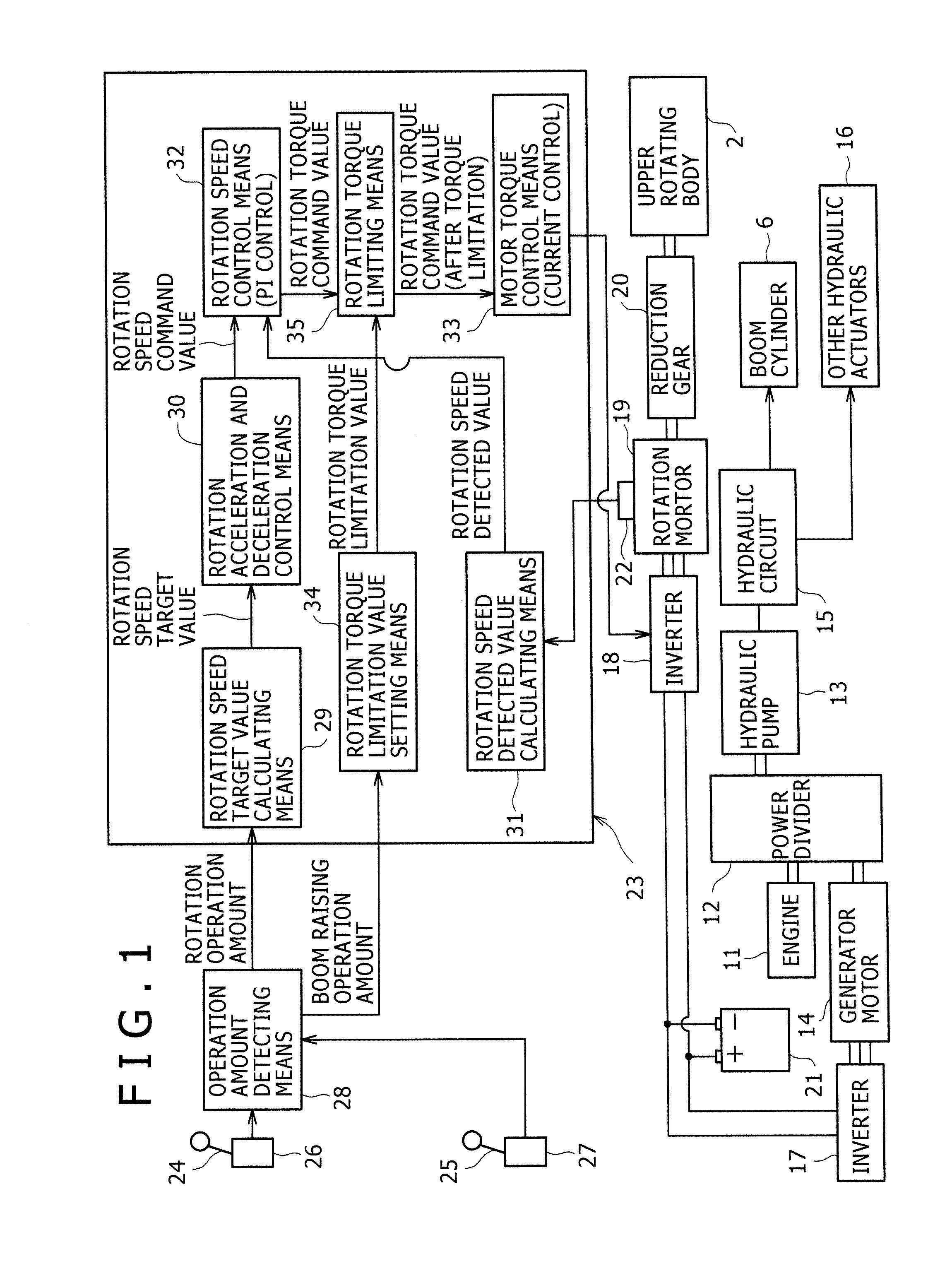
[0034]FIG. 1 shows an entire configuration of a rotation control device according to the first embodiment.

[0035]Firstly, when drive system is explained, power of an engine 11 is added to a hydraulic pump 13 and a generator motor 14 through a power divider 12.

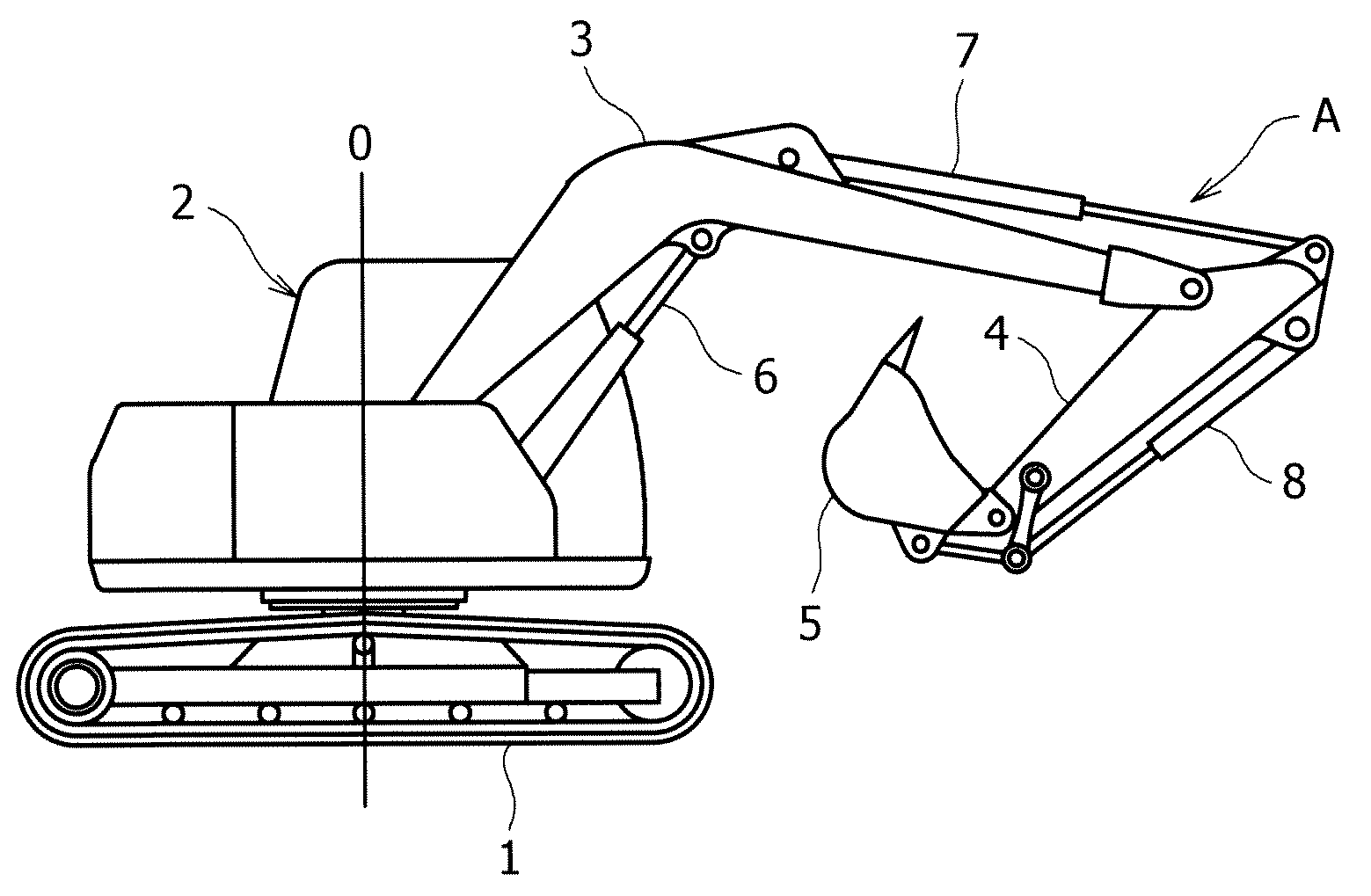
[0036]A hydraulic circuit 15 is connected to the hydraulic pump 13, and a boom cylinder 6 shown in FIG. 7 and other hydraulic actuators (given the reference numeral 16 in total) are driven by pressure oil from the hydraulic pump 13.

[0037]Power from the generator motor 14 is sent to a rotation motor 19 through both a generator motor inverter 17 and a rotation motor inverter 18. Torque of the rotation motor 19 is transmitted to an upper rotating body 2 through a reduction gear 20, and the upper rotating body 2 is rotated around a vertical axis O shown in FIGS. 7 and 8.

[0038]A battery 21 is provided between both the inverters 17 and 18. The battery 21 is combined with the generator motor 14 and used as a power source for the rotati...

second embodiment

[0055]In the second embodiment shown in FIGS. 4 to 6, the same parts as in the first embodiment are given the same reference numerals and repeated explanation thereof is omitted.

[0056]When different points from the first embodiments are explained, as understood from comparison between FIGS. 1 and 4, rotation acceleration limitation value setting means 36 is provided instead of the rotation torque limitation value setting means 34 of the first embodiment.

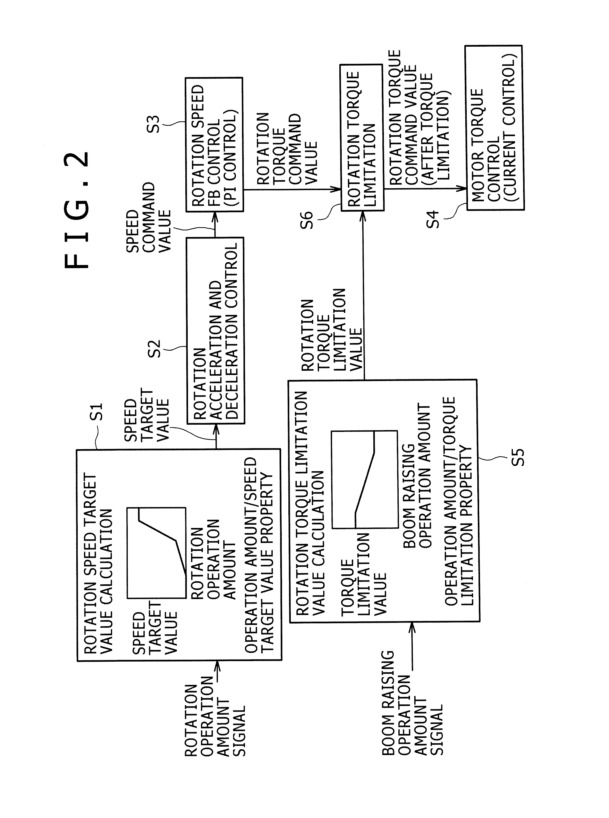
[0057]The rotation acceleration limitation value setting means 36 is adapted to determine an acceleration limitation value from a property of boom raising operation amount / torque limitation value which is preset on the basis of the boom raising operation amount, and send the acceleration value to the rotation acceleration and deceleration control means 30, as Control Step S5′ in FIG. 5 instead of Control Step S5 in FIG. 2.

[0058]In the rotation acceleration and deceleration control means 30 receiving the acceleration limitation value,...


PUM


Abstract

In a rotation control device for rotating a rotation motor at speed in accordance with a boom raising operation amount, at the time of a combined operation for simultaneously performing a rotation action and a boom raising action, a limitation value of rotation torque in accordance with the boom raising operation amount is determined by rotation torque limitation value setting means of a controller, the limitation value serving as a rotation torque limitation value is sent to rotation speed control means, and a command value of the rotation torque is torque-limited by rotation torque limiting means.

Description

BACKGROUND OF THE INVENTION[0001]1. Field of the Invention[0002]The present invention relates to a hydraulic / electric combination type rotation control device for a working machine of simultaneously using a hydraulic action by a hydraulic actuator and a rotation action by an electric motor.[0003]2. Description of the Related Art[0004]THE RELATED ART will be described taking an excavator as an example.[0005]The excavator is, as shown in FIGS. 7 and 8, is configured such that an upper rotating body 2 is rotatably mounted on a crawler type lower traveling body 1 around a vertical axis O. On the upper rotating body 2, is installed an excavating attachment A provided with a boom 3, an arm 4, a bucket 5, a boom cylinder 6, an arm cylinder 7, and a bucket cylinder 8.[0006]Instead of a total hydraulic drive method in which all the actions are performed by a hydraulic actuator driven by a hydraulic pump in the excavator, as proposed in WO2006 / 004080A1 (hereinafter, referred to as Patent Docu...

Claims


Application Information

Patent Timeline
Patent Type & Authority Applications(United States)
IPC IPC(8): G06F19/00E02F9/22
CPCE02F9/123E02F9/2075E02F9/2025
Inventor KAGOSHIMA, MASAYUKIKOMIYAMA, MASAYUKI
Owner KOBELCO CONSTR MASCH CO LTD
Why Eureka
Try Eureka