Devices and methods for device-mapping connectivity hub

a connectivity hub and device technology, applied in the field of devices and methods for device-mapping connectivity hubs, can solve the problems of not many educational institutions able to afford to provide a computer for each user, inconvenient to bring students' own computers to the classroom, and high cost of providing such equipmen

Active Publication Date: 2008-04-03
WESTERN DIGITAL ISRAEL LTD
View PDF19 Cites 10 Cited by
  • Summary
  • Abstract
  • Description
  • Claims
  • Application Information

AI Technical Summary

Benefits of technology

[0037]In another preferred embodiment of the present invention, the connectivity hub includes controllable mechanical or electronic switches on the VCC lines to each of the physical ports. When the host system needs to identify the volumes mounted into the connectivity hub and link the volumes to physical ports, the host system disconnects the VCC to all the UFDs via the switches, and then turns the VCC to each port on again one by one. Each port that is powered up will initiate the mounting process of the volume that is plugged into the port. This enables the host system to identify the volumes as they appear, and thus link each volume with the port that has been most recently powered on. As an example, if the host system uses this procedure to detect one port per second, the host system can map a 100-port connectivity hub in less than two minutes.

Problems solved by technology

However, not many educational institutions can afford to provide a computer for each user in the classroom.
Requiring students to bring their own computers to the classroom is impractical.
Due to the complexity of the IT equipment, providing such equipment is costly and can take considerable time and effort.
Existing IT limit the computer-based learning processes to equip these educational institutions, such as classrooms, with a computer per-user.
All the prior-art references cited above do not teach methods for identifying the relative physical locations of storage devices engaged in a port hub, nor do they teach methods for mapping such locations to the logical identities of the storage devices.

Method used


Image

  • Devices and methods for device-mapping connectivity hub
  • Devices and methods for device-mapping connectivity hub
  • Devices and methods for device-mapping connectivity hub

Examples


Embodiment Construction

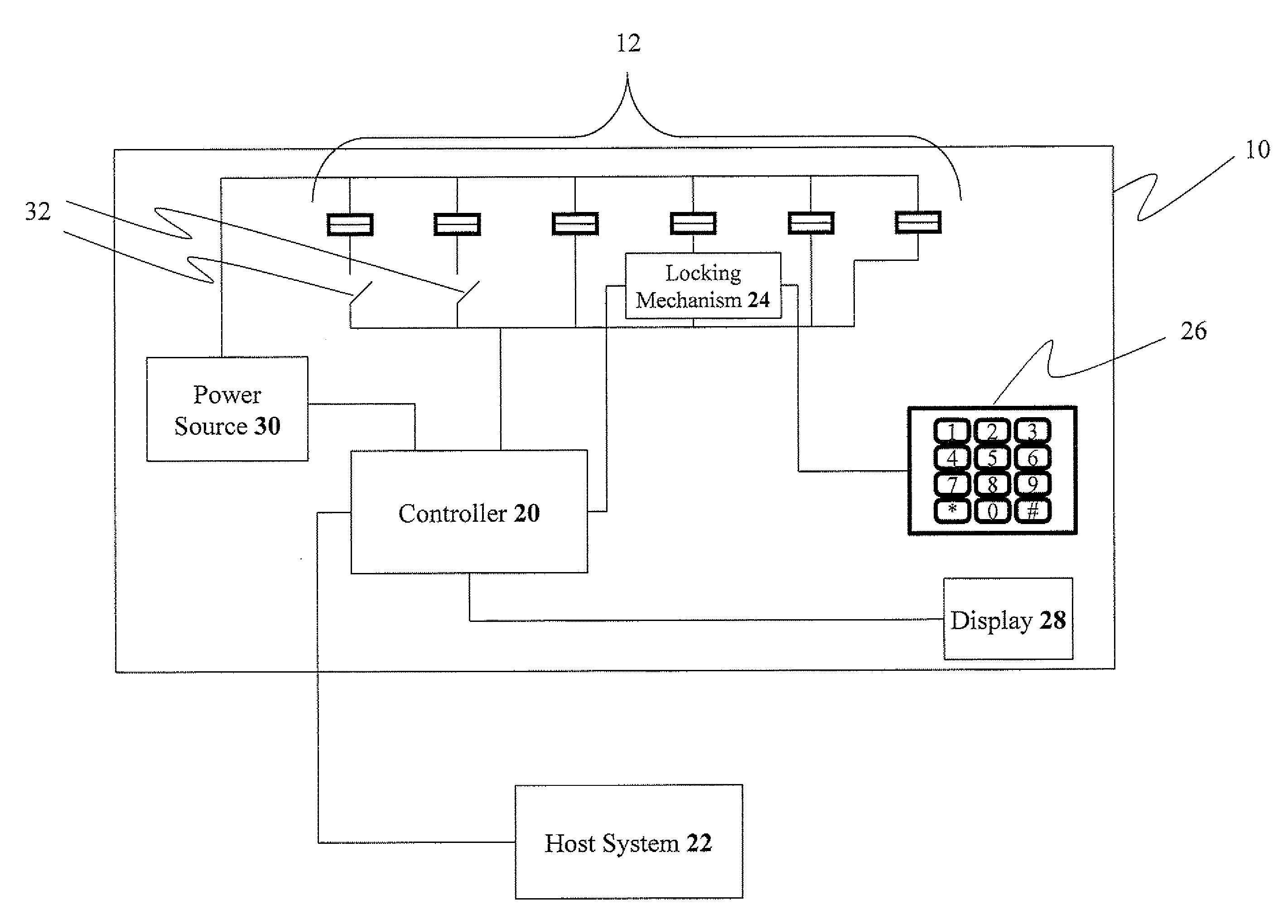
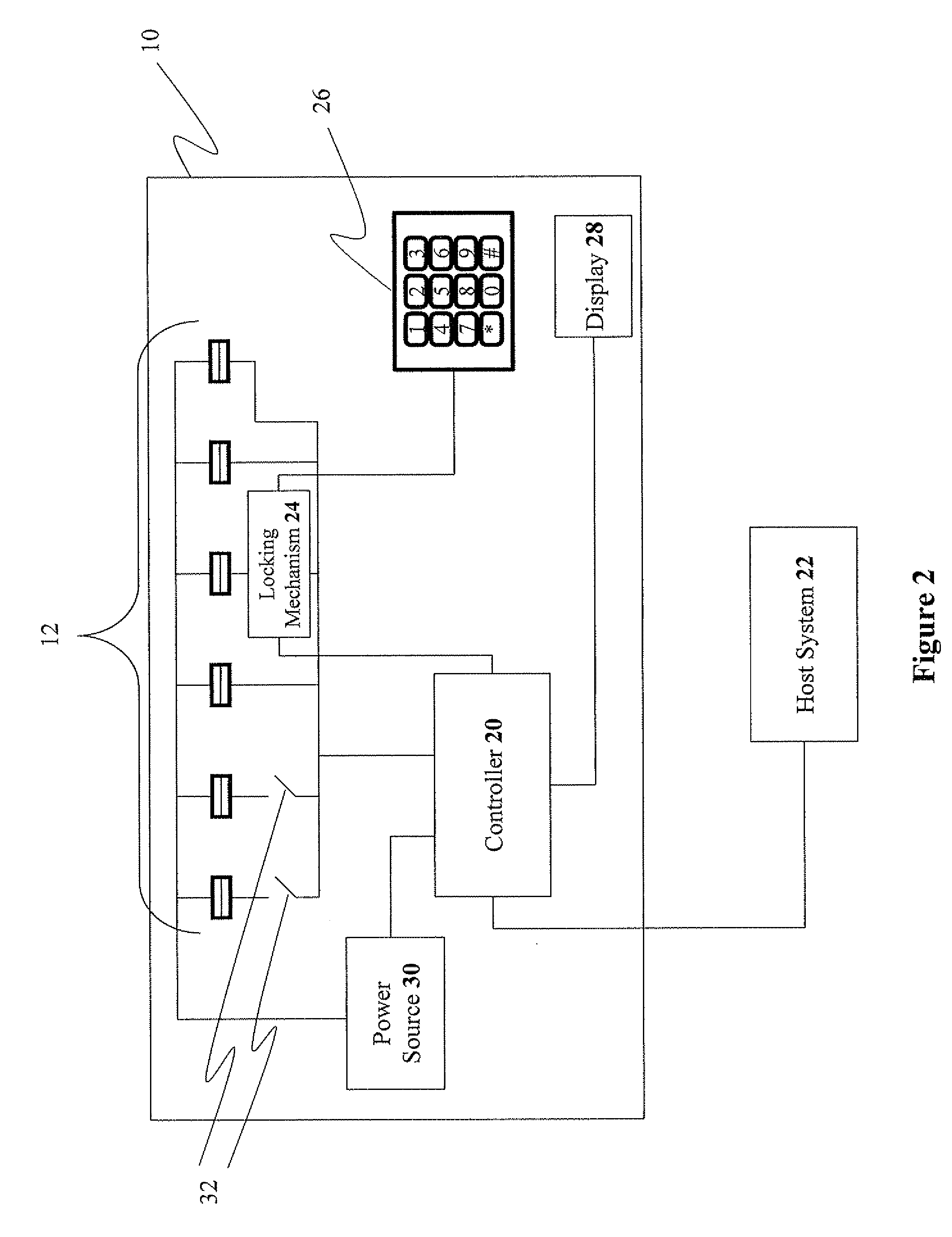
[0090]The present invention relates to devices and methods for providing user-specific connectivity, to a plurality of storage devices, for a plurality of end-users in a room. The principles and operation for providing user-specific connectivity for a plurality of end-users in a room, according to the present invention, may be better understood with reference to the accompanying description and the drawings.

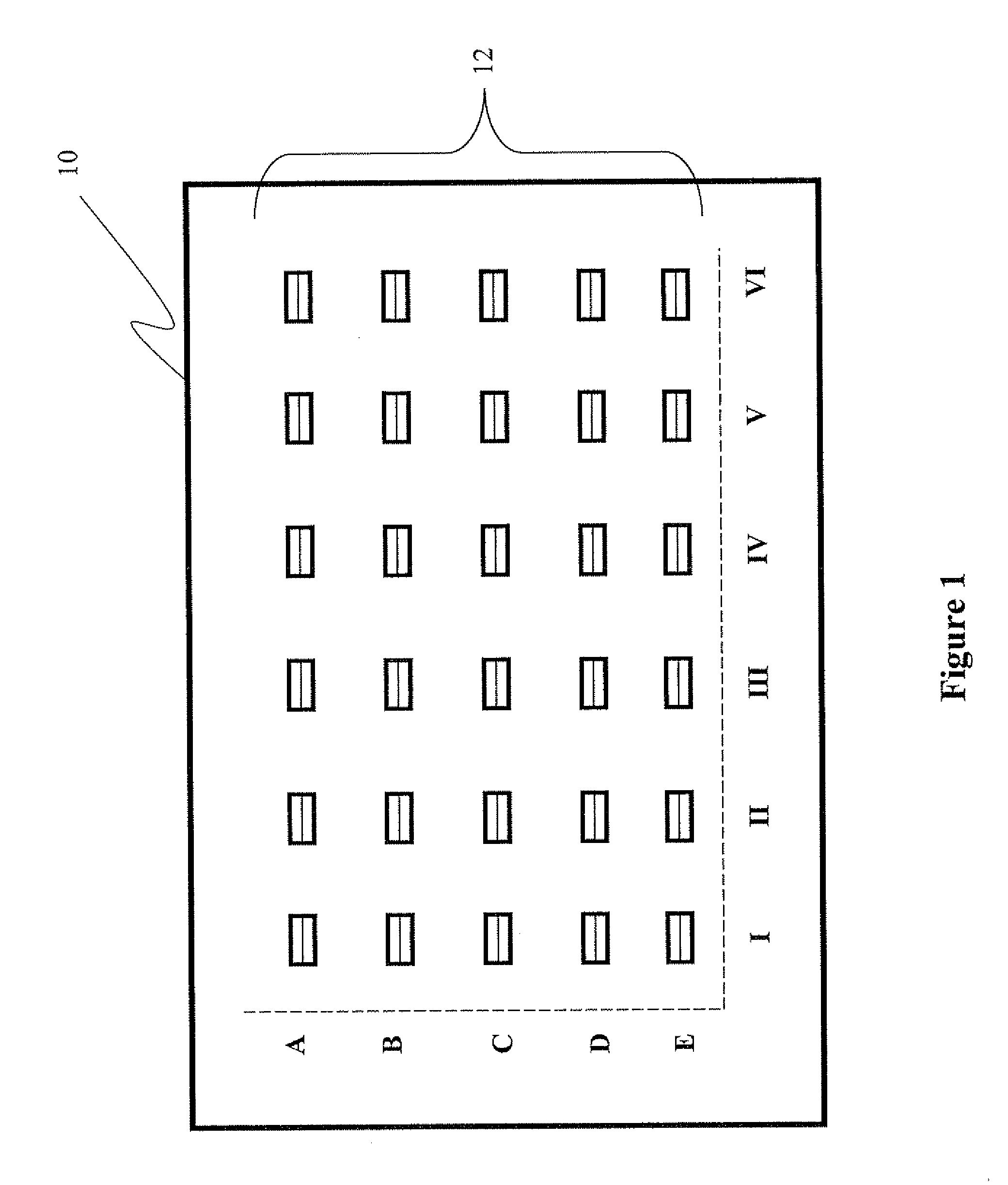
[0091]Referring now to the drawings, FIG. 1 is a simplified schematic block diagram of a device-mapping connectivity hub, according to preferred embodiments of the present invention. A device-mapping connectivity hub 10 is shown in FIG. 1 having multiple ports 12 for connecting a plurality of PSDs. As an example, hub device 10 is configured with a total of 30 ports 12 in rows A, B, C, D, and E and columns I, II, III, IV, V, and VI, according to the layout of seats in a classroom.

[0092]A user entering the classroom connects his / her PSD into a respective port 12 in connectivity hub...


PUM


Abstract

The present invention discloses devices and methods for a connectivity hub, for connecting a plurality of storage devices to a host system, including: a plurality of ports, each port operative to electrically engage with a storage device; electrical paths joining the plurality of ports to a common point operationally connected to the host system; and a controller operative to associate a relative physical location with a logical identity for each port. Preferably, the controller is configured to perform the association by correlating an insertion time of the storage device in a respective port with a detection time of the logical identity. A connectivity hub, for connecting a plurality of storage devices to a host system, including: at least 23 ports, each port operative to electrically engage with a corresponding storage device; and electrical paths joining at least 23 ports to a common point operationally connected to the host system.

Description

[0001]This patent application claims priority under 35 U.S.C. § 119(e) to U.S. Provisional Application No. 60 / 827,220 filed Sep. 28, 2006, which is hereby incorporated by reference in its entirety.FIELD AND BACKGROUND OF THE INVENTION[0002]The present invention relates to devices and methods for providing user-specific connectivity, to a plurality of storage devices, for a plurality of end-users in a room.[0003]In recent years, the information technology (IT) industry has been rapidly expanding. In an effort to provide significant benefits to the classroom environment, educational institutions have taken advantage of advanced IT tools to integrate computers into the mainstream of the learning process. Providing such technology within the classroom environment enables a teacher to: more easily distribute information to the students, receive information (such as homework assignments) from the students, identify each student, and check attendance, for example.[0004]However, not many ed...

Claims


Application Information

Patent Timeline
Patent Type & Authority Applications(United States)
IPC IPC(8): G06F13/00G06F21/00
CPCG06F3/0605G06F3/0688G06F3/0664
Inventor ALROD, IDANPOMERANTZ, ITZHAKACHSAF, NITZANTEICHER, MORDECHAI
Owner WESTERN DIGITAL ISRAEL LTD
Why Eureka
Try Eureka