Tensioned touch panel and method of making same

a touch panel and tensioning technology, applied in the field of touch systems, can solve the problems of unsatisfactory contact, unsatisfactory tensioning, and increased difficulty in adjusting the tension, and achieve the effect of uniform tension and reducing manufacturing and labor costs

Active Publication Date: 2008-04-10
SMART TECH INC (CA)
View PDF14 Cites 37 Cited by
  • Summary
  • Abstract
  • Description
  • Claims
  • Application Information

AI Technical Summary

Benefits of technology

[0017] The tensioned touch panel and method provide advantages in that an overall uniform tension can be maintained in the conductive membrane while reducing manufacturing and labour costs of the tensioned touch panel. As a result, slack is inhibited from developing in the conductive membrane regardless of environmental conditions while maintaining activation forces at user acceptable levels.

Problems solved by technology

Changes in environmental conditions such as humidity and / or temperature may also cause the tensioned membrane to expand resulting in slack developing in the tensioned membrane.
If the tensioned membrane sags or expands, the slack developed in the tensioned membrane may result in undesirable contact between the tensioned membrane and the conductive substrate.
This problem becomes more severe as the size of the touch panel becomes greater.
Although the use of insulating spacer dots maintains separation between the tensioned membrane and the conductive substrate, the use of insulating spacer dots is problematic.
Thus, the insulating spacer dots interrupt the active contact area of the touch panel.
As a result, contacts with the tensioned membrane over insulating spacer dots will not register as contacts since the tensioned membrane cannot be brought into electrical contact with the conductive substrate at those contact points.
Also, the use of insulating spacer dots to separate the tensioned membrane and the conductive substrate is expensive.
It is also difficult to maintain an even spacing between the tensioned membrane and the conductive substrate over the active contact area using insulating spacer dots.
Although the above references show touch panels having mechanisms to maintain tension in the conductive membrane, manufacturing and labour costs are associated with these tensioning mechanisms.

Method used


Image

  • Tensioned touch panel and method of making same
  • Tensioned touch panel and method of making same
  • Tensioned touch panel and method of making same

Examples


Embodiment Construction

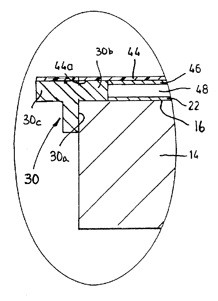
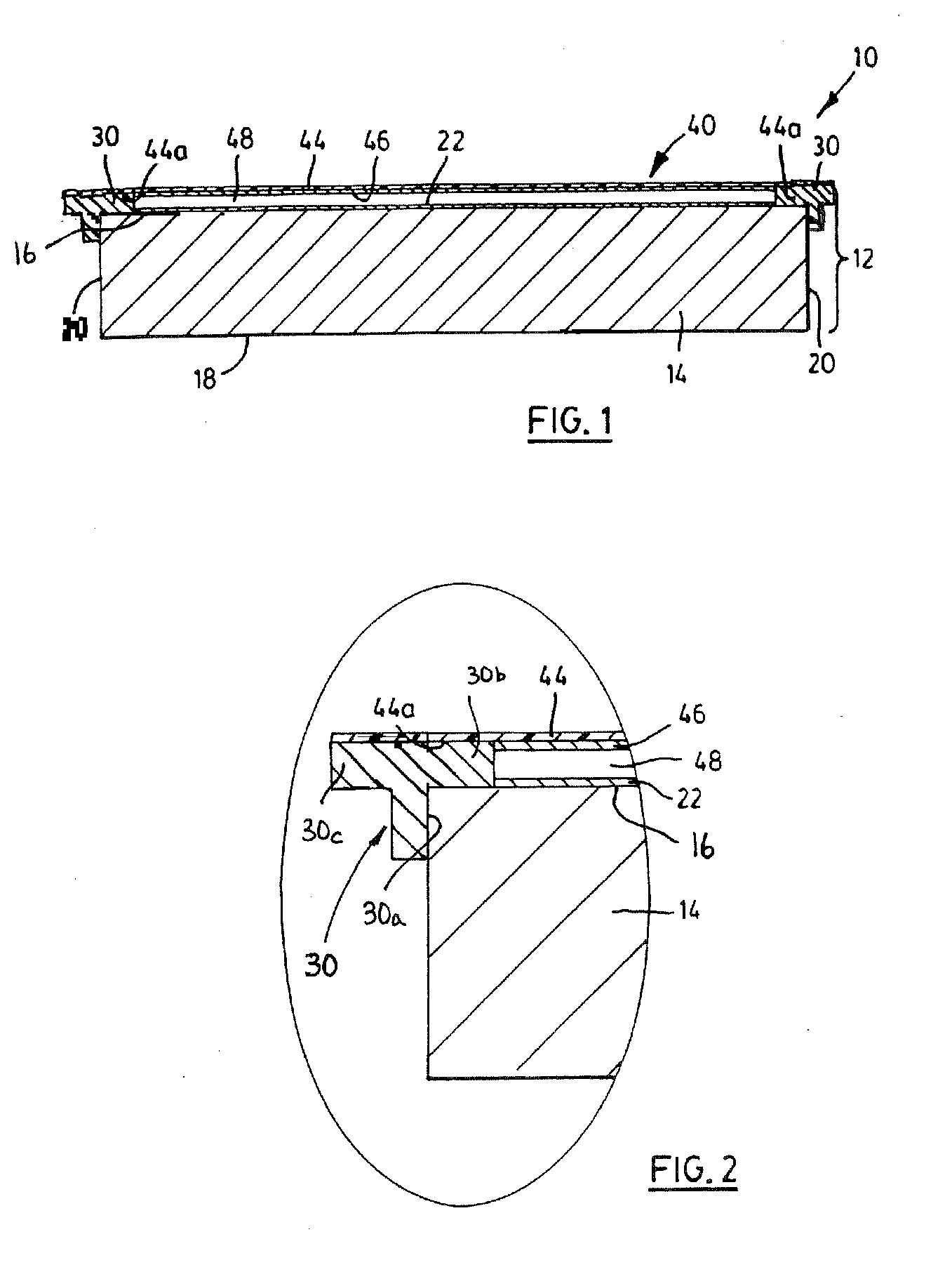
[0028] Turning now to FIGS. 1 and 2, a tensioned touch panel is shown and is generally identified by reference numeral 10. Touch panel 10 in this embodiment is generally rectangular and includes a support structure 12. Support structure 12 comprises a substrate 14 having a major top surface 16, a major bottom surface 18 and side surfaces 20 bridging the top and bottom surfaces. The substrate 14 is formed of a rigid stable material such as for example aluminum or other suitable rigid material. A conductive carbon resistive layer 22 is bonded to the top surface 16 of the substrate 14 via an adhesive. A generally continuous, peripheral insulating spacer rail 30 surrounds the periphery of the substrate 14. The insulating spacer rail 30 is formed of electrically insulating material such as for example rigid polyvinyl chloride (RPVC), acrylonitrile butadiene styrene (ABS), acrylic, fiberglass reinforced plastic (FRP) or coated aluminum.

[0029] In this embodiment, as best seen in FIG. 2, t...


PUM

PropertyMeasurementUnit
lengthaaaaaaaaaa
lengthaaaaaaaaaa
temperatureaaaaaaaaaa

Abstract

A tensioned touch panel includes a support structure having a substrate with a generally planer conductive surface disposed thereon and an insulating spacer generally about the periphery of the substrate. A pretensioned conductive member overlies the support structure. The spacer separates the conductive membrane and the conductive surface thereby to define an air gap therebetween. A conductive membrane is secured to the support structure under sufficient tension to inhibit slack from developing in the conductive membrane as a result of changes in environmental conditions. A method of assembling a tensioned touch panel is also provided.

Description

CROSS-REFERENCE TO RELATED APPLICATIONS [0001] This application is a continuation-in-part of U.S. patent application Ser. No. 10 / 834,361 filed on Apr. 24, 2004 for an invention entitled “Tensioned Touch Panel And Method Of Making Same”, the content of which is incorporated herein by reference.FIELD OF THE INVENTION [0002] The present invention relates generally to touch systems and in particular to a tensioned touch panel and method of making the same BACKGROUND OF THE INVENTION [0003] Touch panels such as for example digitizers and analog resistive touch screens that make use of one or more tensioned membranes, are known in the art. Tensioned touch panels of this nature typically include a conductive membrane that is stretched tautly over and spaced from a conductive substrate. When a pointer is used to contact the tensioned membrane with sufficient activation force, the tensioned membrane deflects and contacts the conductive substrate thereby to make an electrical contact. Determi...

Claims


Application Information

Patent Timeline
Patent Type & Authority Applications(United States)
IPC IPC(8): H01H5/00H01R43/00G06F3/033G06F3/045H03K17/96
CPCG06F3/03547G06F3/045Y10T29/49002Y10T29/49128Y10T29/49105Y10T29/49117Y10T29/49155
Inventor AUGER, PAUL A.BUTMIR, AMIR
Owner SMART TECH INC (CA)
Why Eureka
Try Eureka