Crane

a technology of cranes and crates, which is applied in the direction of passenger carriages, braking devices for hoisting equipment, cranes, etc., can solve the problems of uneven increased wear of the track guiding means, and increased wear of the wheel running surfaces,

Active Publication Date: 2008-04-10
HANS KUENZ GMBH
View PDF11 Cites 17 Cited by
  • Summary
  • Abstract
  • Description
  • Claims
  • Application Information

AI Technical Summary

Benefits of technology

[0013]It is the primary object of the invention to provide a connection of the traveling gear groups of the crane traveling gear to the end carriage by means of an economical design accompanied by advantageous transmission of force.

Problems solved by technology

These bore holes constitute interfaces between the mechanical construction of the traveling gear group and the steel construction of the crane frame, which has often proven problematic in practice.
Accordingly, in traveling gears of this kind having multiple wheels, the horizontal forces that must also be absorbed by the rail construction are disadvantageously large.
The occurring axial deviations and the unfavorable distribution of horizontal forces lead to bending in the traveling gear and, accordingly, to increased wear on the track guiding means, the wheel running surfaces, and the rails.
A construction using a live ring with balls or rollers is unobjectionable in technical respects but has a very large structural width and is very disadvantageous in terms of cost.
The use of a sliding bearing support with an additional counter-support for absorbing tilting forces, also already known, has the disadvantage that very high rotational resistances must be overcome.
Because of the high tilting forces, particularly when the corners of the crane are not loaded, very expensive counter-supports are provided in addition.
In this case, it is necessary to pretension the main bearing with very high pretensioning forces over the counterbearing until one-sided lifting of the main bearing is no longer possible.
If the main bearing is lifted only slightly, the entire vertical force is shifted to one or a few rolling bodies which would lead to the destruction of the bearing.
Disadvantages in this construction include the risk of a change in pretensioning forces, e.g., due to settling over the course of crane operation, loading of the balls and of the runway, which practically always occurs at the same point due to the very slight movement of the bearing, and the expensive construction.
One of the disadvantages is this case is that high bearing forces result from the tilting moment because the tension rods can only absorb tensile forces.

Method used


Image

  • Crane
  • Crane
  • Crane

Examples


Embodiment Construction

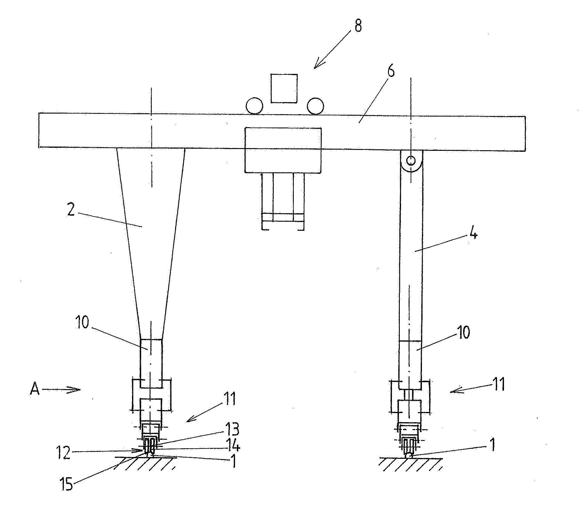
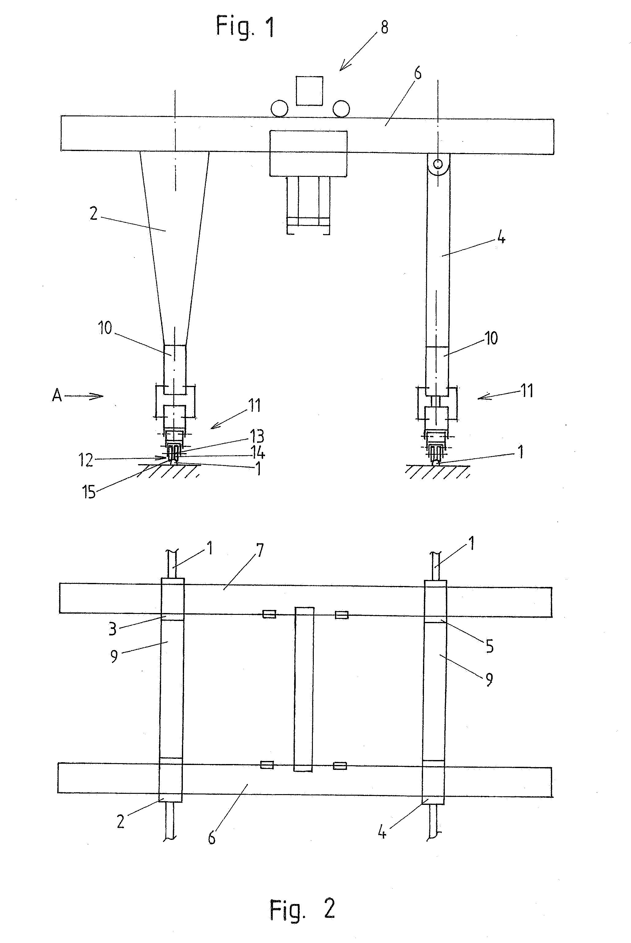
[0026]An embodiment example of the invention is shown in the drawings. The crane is constructed as a gantry crane which can move on a runway formed by two rails 1 laid at a distance from one another. A gantry crane of this kind usually has four legs 2, 3, 4, 5. Constructions with three legs are also known. Further, two supports can also be provided. The legs 2-5 and supports carry the transverse girder or transverse girders 6, 7 along which a trolley 8 is movable or which are provided with another type of movable or fixed hoisting device. When the construction is carried out with two or more transverse girders 6, 7, connection girders 9 extend between the latter.

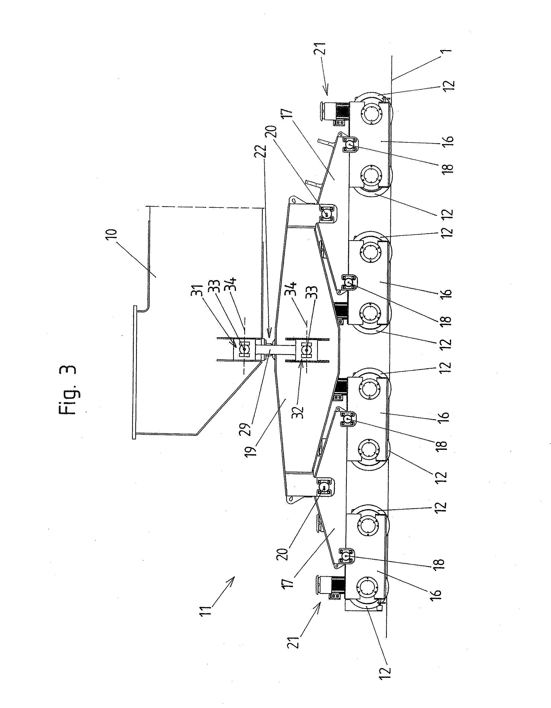
[0027]An end carriage 10 is arranged at the lower ends of the legs 2, 3; 4, 5 arranged on a respective side of the gantry and connects them. The end carriages 10 serve to connect the steel construction of the crane to the individual traveling gear groups 11 of the crane traveling gear. A traveling gear group I of this kind i...


PUM


Abstract

The invention is directed to a crane which comprises a traveling gear which comprises a plurality of traveling gear groups for moving along rails, each traveling gear group having at least two wheels which are rotatably mounted at a subframe so as to be spaced apart in longitudinal direction of the respective rail and are connected to an end carriage by a central joint having at least degrees of freedom for rotating the traveling gear group relative to the end carriage around a vertical axis and for swiveling the traveling gear group relative to the end carriage around a horizontal axis extending at right angles to the rails. According to the invention, the central joint is constructed in vertical direction as a floating bearing so that only horizontal forces can be transmitted by this central joint, and a respective traveling gear group is further connected to a respective end carriage by two connecting rods which are arranged on opposite sides of the central joint viewed in transverse direction of the respective rail and which are connected to the traveling gear group on one side and to the end carriage on the other side by joints lying one above the other, which joints can transmit compressive forces as well as tensile forces and which have at least degrees of freedom for swiveling the connecting rods relative to the traveling gear group and relative to the end carriage, respectively, around a horizontal axis extending at right angles to the respective rail and around a horizontal axis extending parallel to the respective rail.

Description

CROSS-REFERENCE TO RELATED APPLICATION[0001]This application claims priority of German Application No. 10 2006 047 997.1, filed Oct. 9, 2007, the complete disclosure of which is hereby incorporated by reference.BACKGROUND OF THE INVENTION[0002]a) Field of the Invention[0003]The invention is directed to a crane comprising a traveling gear for moving along rails which has a plurality of traveling gear groups, each having at least two wheels which are rotatably mounted at a subframe so as to be spaced apart from one another in longitudinal direction of the respective rail and which are connected to an end carriage of the crane by a central joint having at least degrees of freedom for rotating the traveling gear group relative to the end carriage around a vertical axis and for swiveling the traveling gear group relative to the end carriage around a horizontal axis extending right angles to the rails.[0004]b) Description of the Related Art[0005]Traveling gear of rail-bound cranes, partic...

Claims


Application Information

Patent Timeline
Patent Type & Authority Applications(United States)
IPC IPC(8): B66C17/00
CPCB61F5/16B66C19/002B66C9/16B66C5/02
Inventor LERCHENMUELLER, PETER
Owner HANS KUENZ GMBH
Why Eureka
Try Eureka