
Electroluminescence-equipped article

a technology of electroluminescent film and equipment, applied in the field of electroluminescent units and articles, can solve the problems of large amount of effort required to fit each individual part, inconvenient installation, and inability to weatherproof electroluminescent films

Inactive Publication Date: 2008-04-10
EVONIK DEGUSSA GMBH
View PDF5 Cites 45 Cited by
  • Summary
  • Abstract
  • Description
  • Claims
  • Application Information

AI Technical Summary

Benefits of technology

[0013]In another embodiment, the present invention relates to an illuminated article, comprising the above electroluminescent unit.
[0022]DC / AC inverter and electronic ON / OFF switch or switches,
[0022]DC / AC inverter and electronic ON / OFF switch or switches,
[0022]DC / AC inverter and electronic ON / OFF switch or switches,

Problems solved by technology

This equipment has the disadvantage of a large amount of effort required to fit each individual part to the piece of clothing, in order to ensure portability.
The connecting cables between the components of the device must be drawn through the piece of clothing, or must be sewn to it, which requires effort.
The seams by means of which the electroluminescent films are fixed to the piece of clothing can be made waterproof or weather-resistant in general only with particular additional effort, and electroluminescent films are not weather-resistant per se.
The life of an electroluminescent device such as this on pieces of clothing can be achieved only with a large amount of additional effort.
However, safety clothing is in fact frequently subject to severe conditions during use, and the life of a device such as this is therefore restricted, or even unsatisfactory, owing the poor resistance to wear.
In addition, the energy source is connected by means of a clamping or plug-in apparatus, which restricts the robustness of this type of assembly and makes it susceptible to wear, in terms of the clamping and plug-in connections becoming loose or dirty.
However, a procedure such as this in the first case restricts the mobility and portability of the object equipped in this way, or, in the second case, is becoming increasingly undesirable nowadays in terms of the requirements for environmental protection and resource conservation.
The disadvantage of this arrangement is that it has little flexibility, or lacks flexibility, restricting use to items of everyday use which are likewise inflexible.

Method used


Image

  • Electroluminescence-equipped article
  • Electroluminescence-equipped article
  • Electroluminescence-equipped article

Examples


Embodiment Construction

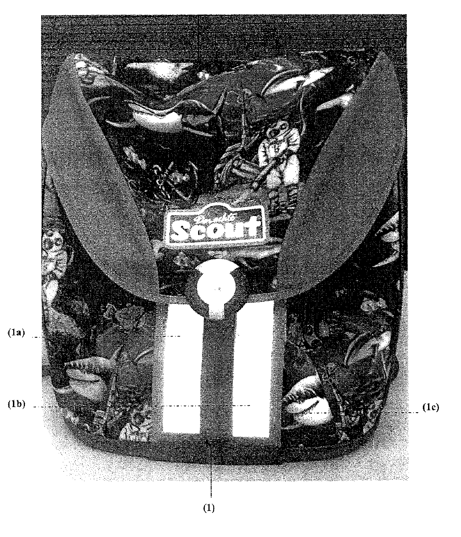
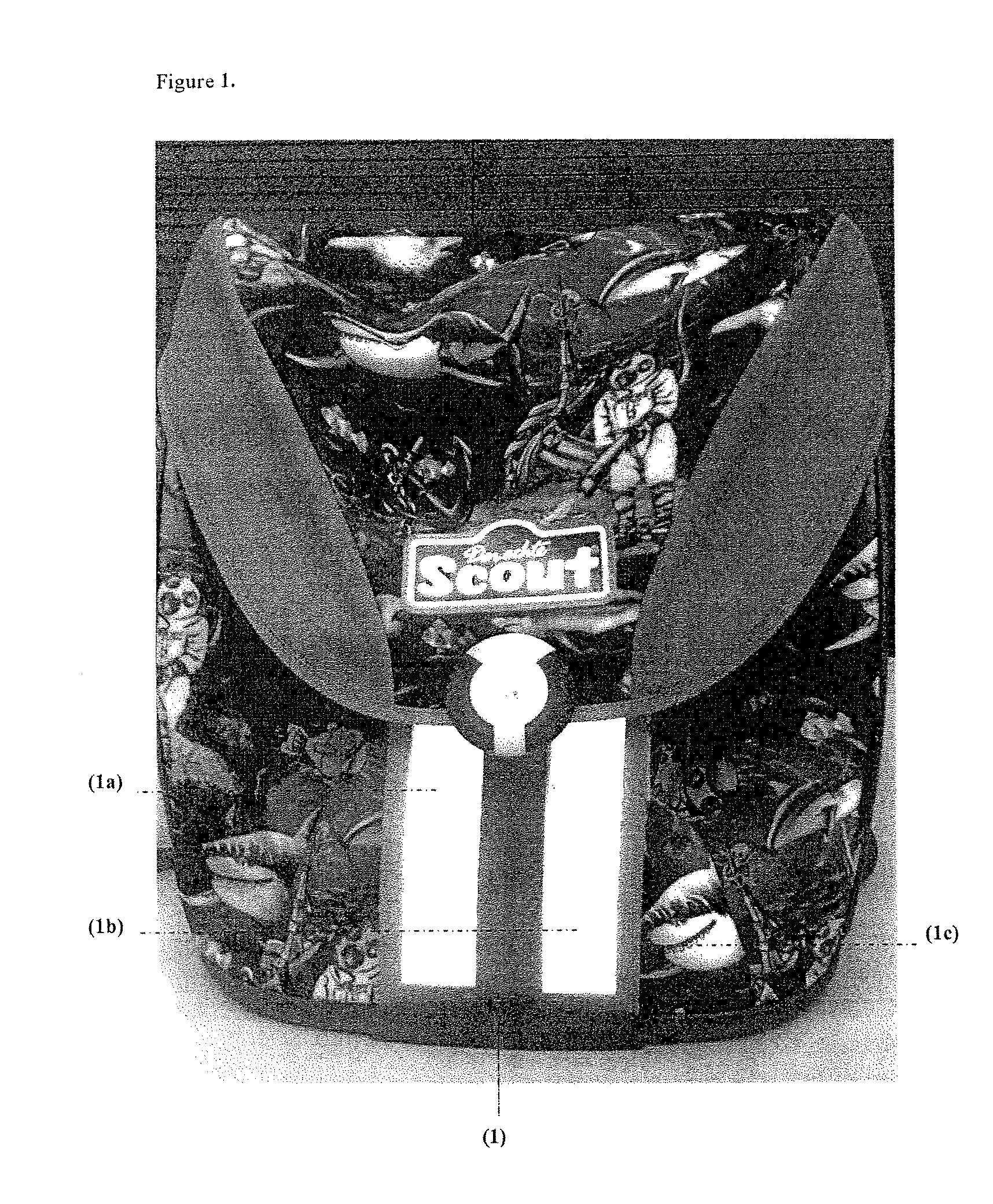
[0016]The present invention relates to an electroluminescent unit comprising an energy source, an electronic drive, and at least one electroluminescent film in a transparent sheath.

[0017]For the purposes of the present invention, an “electroluminescent unit” should be understood as meaning an arrangement which has the components required for operation of an electroluminescent film or films, has the electroluminescent film or films, and has a transparent sheath which sheathes all of the components as well as the electroluminescent films jointly.

[0018]The components which are required for operation of the electroluminescent film or films, such as[0019]electroluminescent film or films,[0020]energy source,[0021]electronic drive, comprising[0022]DC / AC inverter and electronic ON / OFF switch or switches,[0023]electronic charging apparatus or unit,[0024]connecting cable or cables,

may be combined in a transparent sheath.

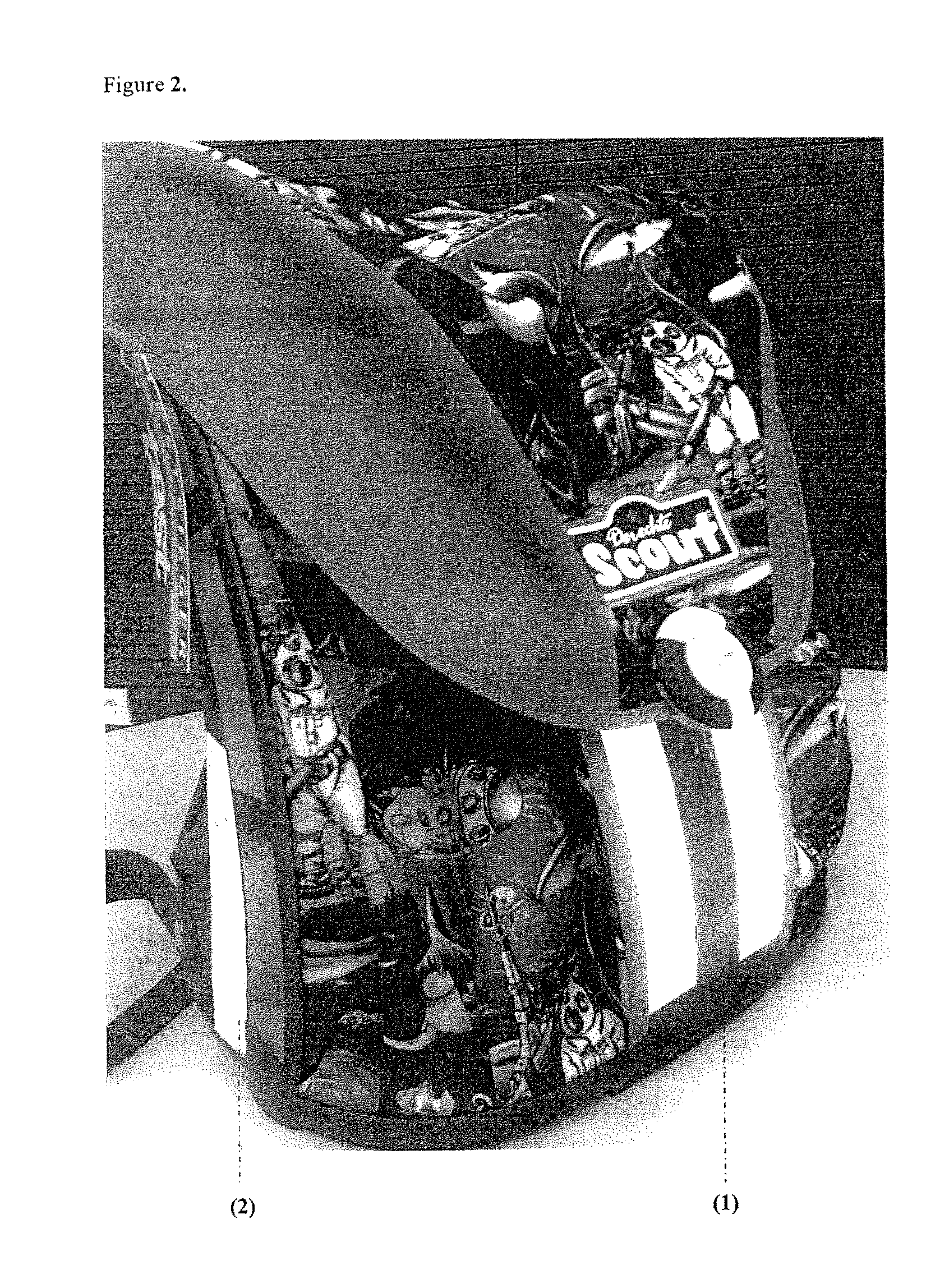
[0025]An illuminated article may comprise the electroluminescent unit acc...


PUM


Abstract

An electroluminescent unit, containing a) an energy source; b) an electronic drive; and c) at least one electroluminescent film in a transparent sheath are useful in illuminated articles, in particular transport containers and items for everyday use.

Description

BACKGROUND OF THE INVENTION[0001]1. Field of the Invention[0002]The present invention relates to electroluminescent units and articles equipped with them.[0003]2. Discussion of the Background[0004]Electroluminescent films are described in detail in the literature. Such electroluminescent films include the required energy sources and electronic circuits, inverters constructed in a microminiaturized or discrete form, which produce the AC voltage required for operation of the electroluminescent films, as well as further electronic circuits for various operating modes of the electroluminescent films.[0005]For example, DE 296 00 047 U1 discloses a visual safety and signaling device in which an electroluminescent film is powered by a battery, to which an inverter and a controller, to which a control unit can be added, are connected. By way of example, a jacket or, in an entirely general form, safety clothing, can be equipped with a device such as this. The components of this device are fi...

Claims


Application Information

Patent Timeline
IPC IPC(8): F21V9/16H01J1/62
CPCG09F13/22
Inventor GUTSCH, ANDREASSCHULZE, MICHAELGEIPEL, GERHARDKRAUSE, ROLF
Owner EVONIK DEGUSSA GMBH
Learn More