Trick Dam

a circuitous motion and load technology, applied in water-power plants, mechanical equipment, machines/engines, etc., can solve the problems of limited scalability, limited efficiency, overly complicated and limited efficiency, etc., and achieve the effect of reducing the cost of construction

Inactive Publication Date: 2008-04-10
HENDERSON GARY ALLEN
View PDF5 Cites 7 Cited by
  • Summary
  • Abstract
  • Description
  • Claims
  • Application Information

AI Technical Summary

Benefits of technology

[0051]The first design objective of the rotors is to facilitate low energy ascent or, return to the top transfer point, with sufficient velocity, to overcome drag, and temperature related changes in fluid density, in the shortest possible cycle. I have chosen buoyancy as the method for this basic system, but other methods may be used. The second design objective of the rotors is to fall effectively during the descent phase, overcoming drag, channel pressure, and repeated high velocity impacts at the base. The third design objective of the rotors is to ease the burden of the gateways design, and provide the level of system reliability desired.
[0053]The choice of rotor materials optimizes the rotors gravitational potential at each end of the cycle. Variable attributes include materials, size, construction method, and dynamics both aero and hydro. The design efficiencies also allow for a simple rotor with a metallic shell, trapping a very low-density gas, or vacuum, or a complex material with all properties integrated into a moldable medium. Perhaps such a moldable material would be Styrofoam, doped with magnetizable domains of metal. An engineered design would most likely be shell of rotationally molded polyethylene and a magnetizable low-density core of doped syntactic foam. However, the basic design does not require the magnetic properties, but instead simply maximizes the weight of the rotor by optimization of its properties.
[0081]Here the TD design is used in a small format, as a battery replacement. The outer case is round to allow the TD to orient itself with the source of gravity. The lower gateway is weighted to allow for automatic correct orientation. The outer case is also filled with lubricant, to facilitate ease of orientation.

Problems solved by technology

However, the primary problem, as I perceive it is in their complexity, limited scalability, efficiency.
U.S. Pat. No. 2,037,973 Grondahal (1935) is an excellent design, but is overly complicated and of limited efficiency.
U.S. Pat. No. 5,753,978 Lee (1998) also incorporates many excellent design features, but the design although scalable, lacks the robustness for wide spread use.
U.S. Pat. No. 1,708,807 Tatay (1929) is based upon sound principles, but lacks scalability and efficiency.
The primary problem with the Grondahal & Tatay designs, and many other designs (U.S. Pat. No. 6,305,165 Mizuki) that I have reviewed, in my opinion, is their reliance on rigid control mechanism.
Another problem with these designs is in the in-efficient use of the gravitational potentials, by a focus on ascent, and direct drives.
The Lee design does not suffer from these short comings, however, the manual feed nature of the chosen method is not sufficiently robust for widespread application.
In that although it can create a useful conversion of the state of the water, it does not create the water or the characteristics of the water, which propel the boat.
The problems with my earlier inventions were in the PEC, the need for traffic, and the PRS the need for deep-water operations.
I concluded that the energy of a falling object has the greatest potential for capture, but the way to efficiently move an object to a height, which was not naturally elevated, like a footstep, was the challenge.
But in most cases, I determined that net energy potentials would be insignificant if energy was required to raise rotors prior to dropping them.
The energy captured from the fall was from gravity, but how to employ gravity for the ascent was the challenge.
While the commercial success, of the design is yet to be demonstrated, the Trick Dam meets many long-felt but unsolved needs for a useful power source, which are present due to the failure of others to realize its potentials.

Method used


Image

  • Trick Dam
  • Trick Dam
  • Trick Dam

Examples


Embodiment Construction

: TRICK DAM

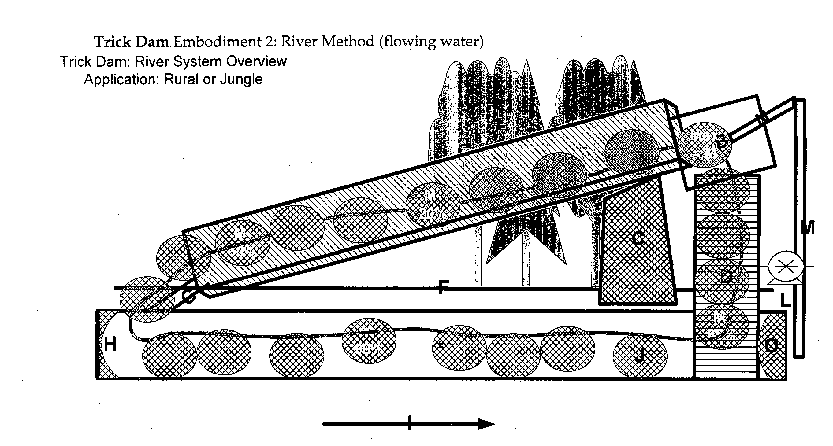
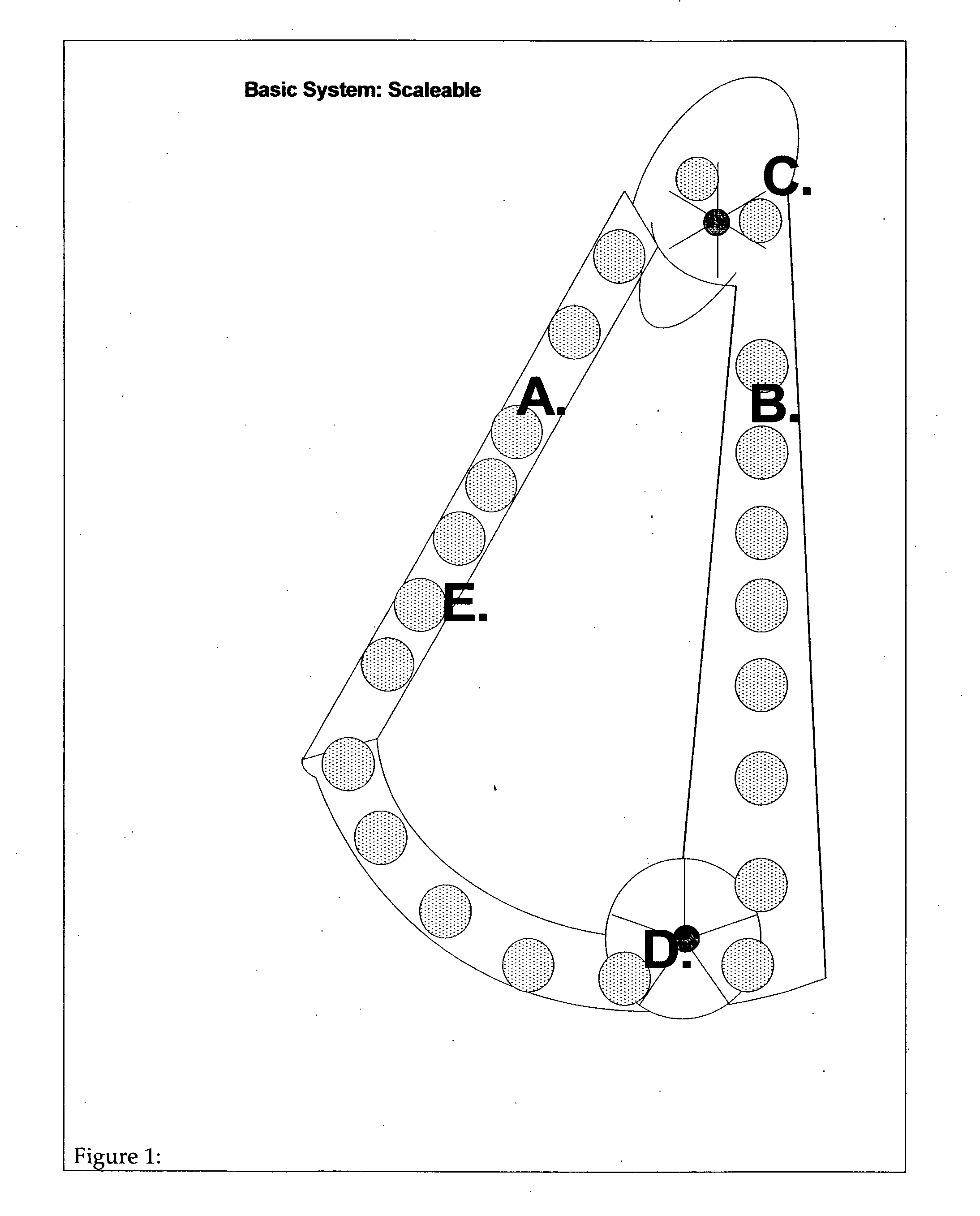
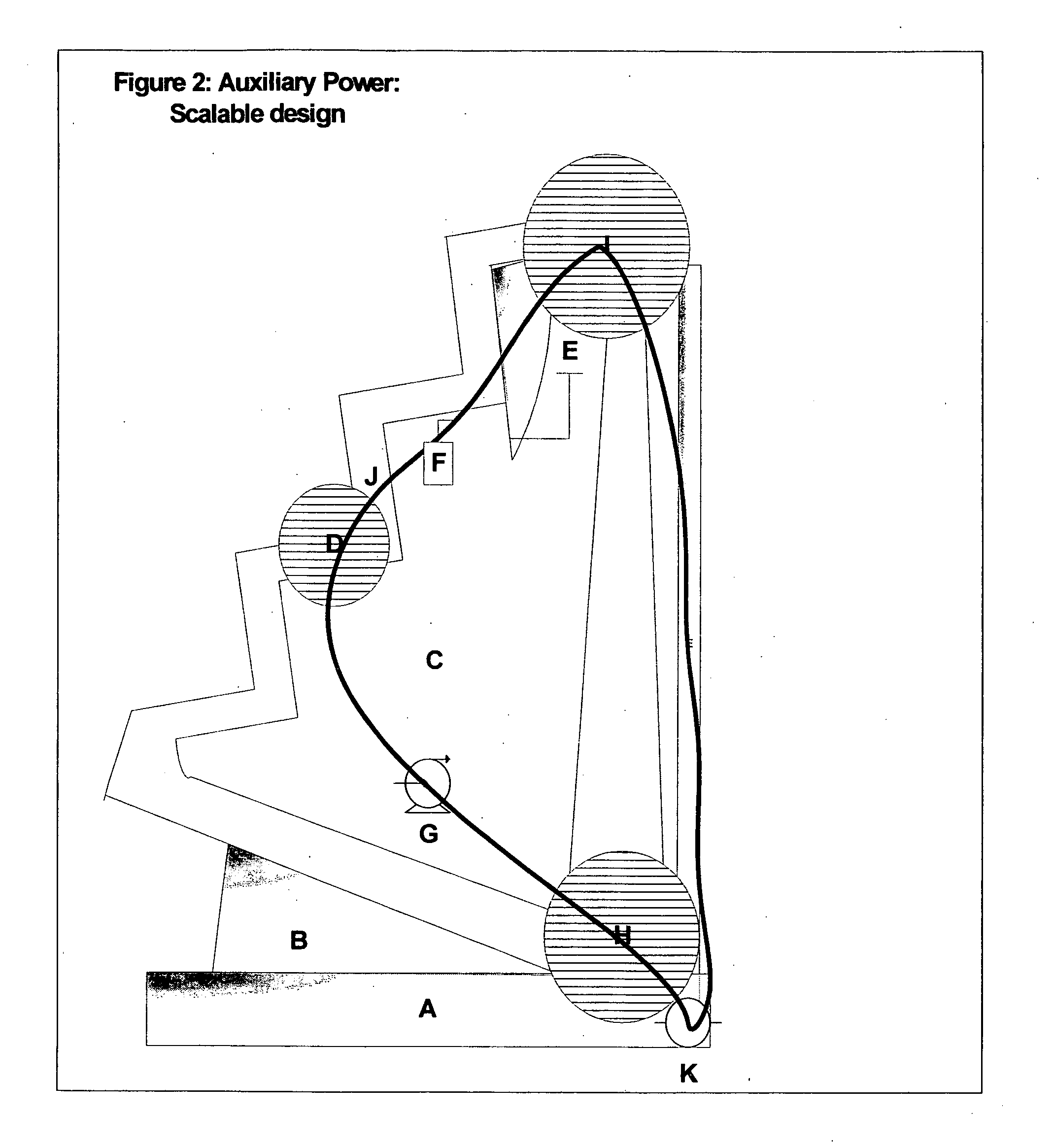
[0033]The Trick Dam is a simple yet powerfully elegant method of generating a continuous load generating cycle, with the least possible moving parts. The Trick Dam is comprised of three elements (FIG. 1: Basic System: Scaleable). These elements are ascent and descent channels, gateways that connect the channels, and a rotor system. I will describe the design steps, and considerations of a basic Trick Dam. It must be noted that the Trick Dam is independent of magnetic induction, although magnetic induction will be discussed here as a pedagogic device.

[0034]The Trick Dam can be primarily constructed from materials suited to a particular application. Plastics, metals, wood, and even paper are useful for channel construction. The channel construction materials must withstand the movement, and impacts of the rotors, while accomplishing the primary goals of the structure. The primary goals in all cases are to present an optimal path for the flow of the rotors through the system...


PUM


Abstract

This patent application describes a method to generate a load bearing repetitive cycle, which in an efficient implementation can provide a scaleable power source for all levels of human society. Only gravity, and construction materials, are necessary for a viable implementation. No additional fuel source is required for its operation. The potentials of the system can best be understood, by imagining the continuous falling of multiple objects weighing anywhere from a few oz to tons. These weights are impacting a paddle wheel, or forcing their way through strong magnetic fields. The energy generating potentials are incredible.The Trick Dam drops a rotor by falling, and then floats the same rotor up to fall again. Thereby concentrating the gravitational potential of a rotor. A self-perpetuating two-step cycle is the result. The momentum of each step is optimized via a manipulation of the rotor's weight, lighter for flotation, and heavier for fall.

Description

CROSS-REFERENCE TO RELATED APPLICATIONS[0001]Not ApplicableBACKGROUND[0002]1. Field of Invention[0003]This invention relates to the generation of loaded circuitous motion, specifically the generation of motion by converting gravity into motion.[0004]2. Description of Prior Art[0005]Since the early 1800's inventors have been developing devices to capture gravitational energy. Many methods are employed, and many have great promise. However, the primary problem, as I perceive it is in their complexity, limited scalability, efficiency. U.S. Pat. No. 2,037,973 Grondahal (1935) is an excellent design, but is overly complicated and of limited efficiency. U.S. Pat. No. 5,753,978 Lee (1998) also incorporates many excellent design features, but the design although scalable, lacks the robustness for wide spread use. U.S. Pat. No. 1,708,807 Tatay (1929) is based upon sound principles, but lacks scalability and efficiency. The primary problem with the Grondahal & Tatay designs, and many other de...

Claims


Application Information

Patent Timeline
Patent Type & Authority Applications(United States)
IPC IPC(8): E02B9/00
CPCF03B17/04Y02E10/20F03G7/10
Inventor HENDERSON, GARY ALLEN
Owner HENDERSON GARY ALLEN
Why Eureka
Try Eureka