
Method for repairing or renewing cooling holes of a coated component of a gas turbine

a technology of coating components and gas turbines, which is applied in the direction of blade accessories, machines/engines, printing, etc., can solve the problems of intensive protection and achieve the effect of increasing the service li

Inactive Publication Date: 2008-04-10
ALSTOM TECH LTD
View PDF22 Cites 49 Cited by
  • Summary
  • Abstract
  • Description
  • Claims
  • Application Information

AI Technical Summary

Benefits of technology

[0016] An object of the present invention is to provide a method for repairing or renewing cooling holes of a coated component of a gas turbine that increased the service life of the repaired or renewed cooling hole.
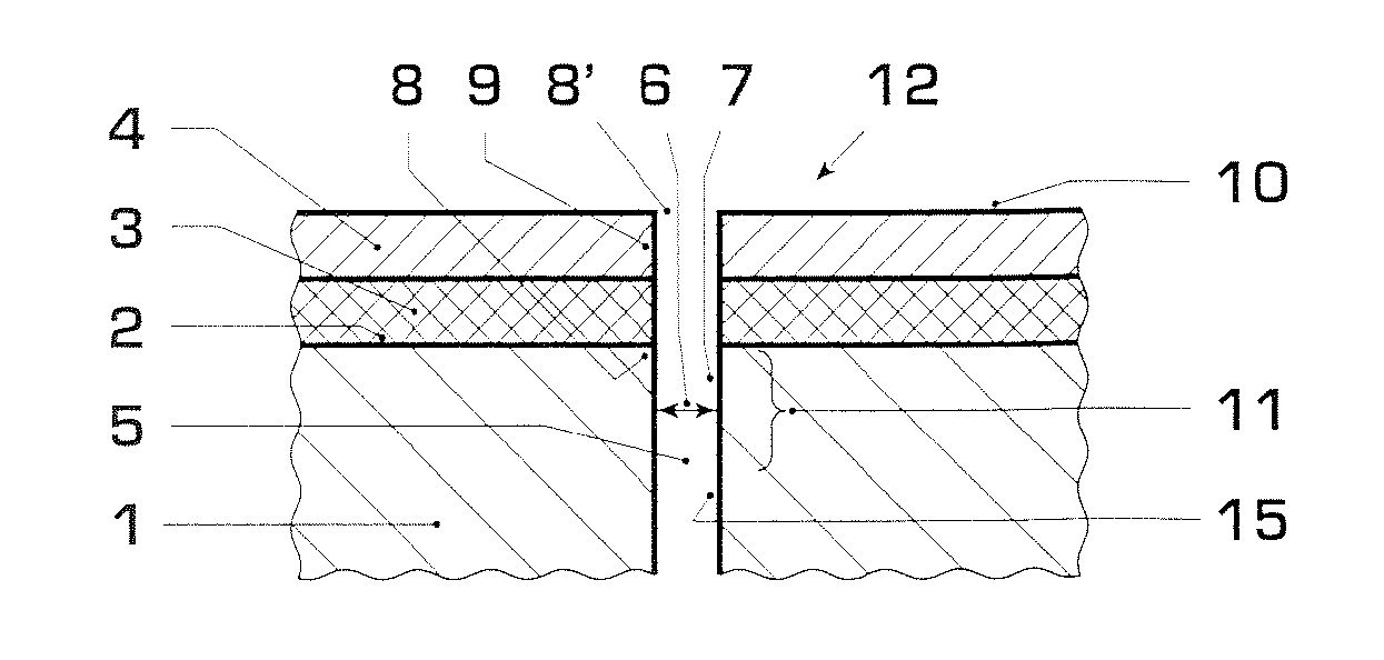
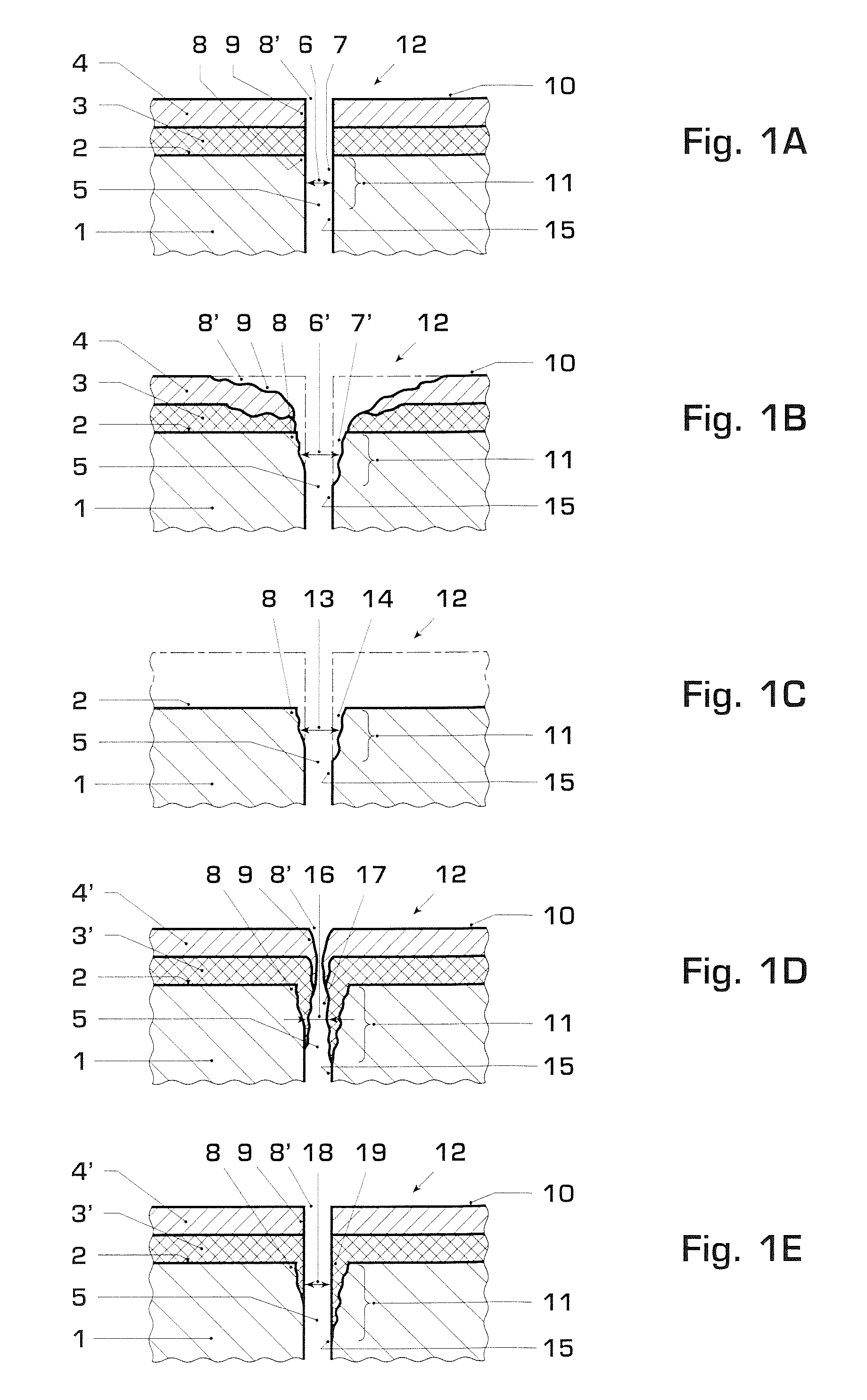
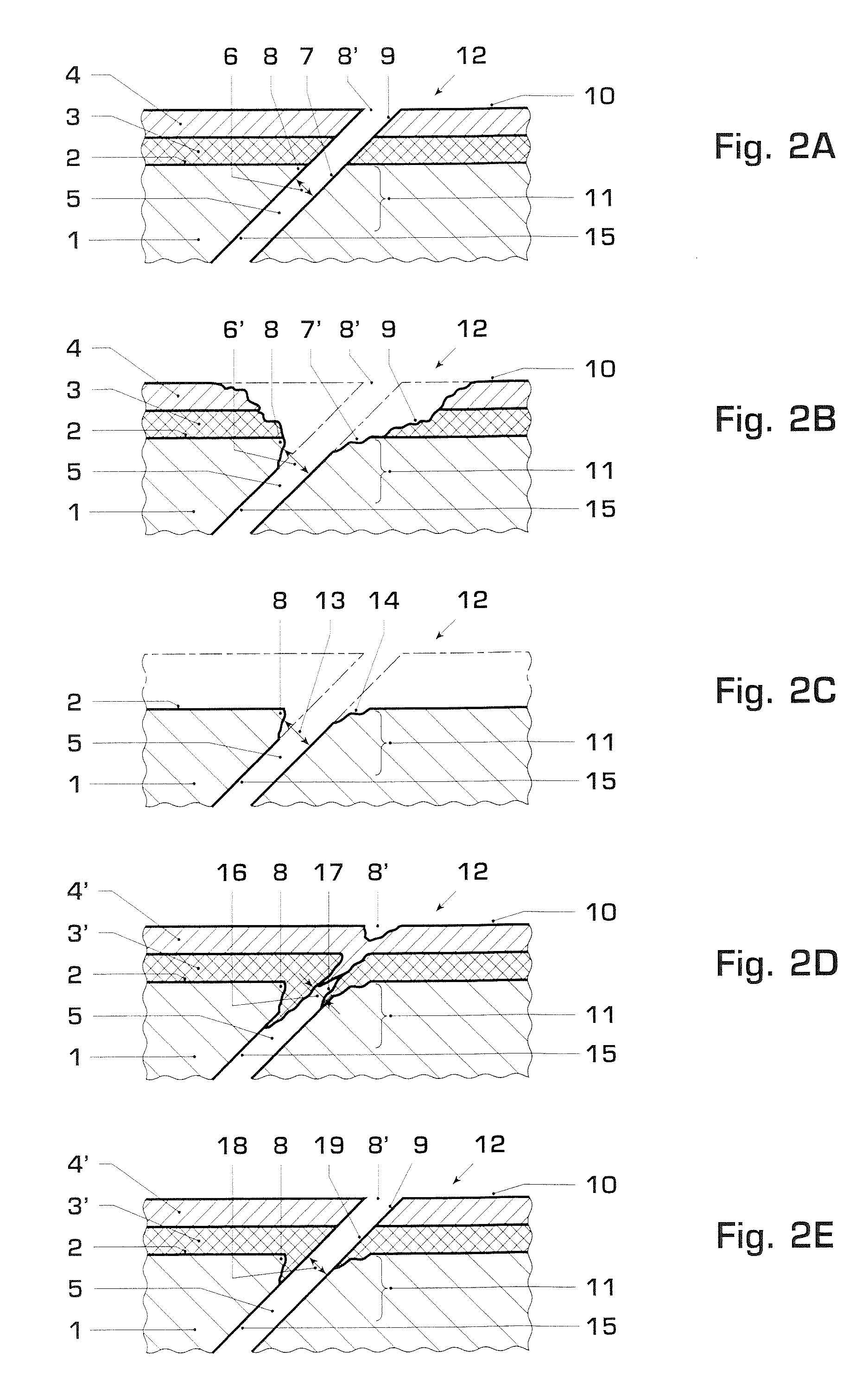
[0017] According to the present invention, the repair or renewal of the cooling holes is performed so that the cooling holes then have basically the same cross sections or basically the same cross sectional contours as in the original unused state of the finished component. At the same time, however, a longitudinal section of the respective cooling hole, which extends to the outer side of the component, is also to be provided with the new coating. The reproduction of the original geometry of the cooling hole provides for the cooling hole being able to optimally fulfil the function for which it is intended. At the same time, the risk of hot operating gas being able to penetrate into the cooling hole is reduced as a result of this. Furthermore, the new coating, which reaches into the longitudinal section of the cooling hole, brings about an intensive protection of the material of the component against the aggressive hot operating gases, if these were to still penetrate into the respective cooling hole. In this way, corrosion of the cooling hole, and therefore a cross sectional widening, can be avoided. A cooling hole cross section which is widened as a result of corrosion during operation of the gas turbine, makes penetrating of the aggressive operating gas into the cooling hole easier, and, as a result, intensifies the corrosive action which leads to an increased further cross sectional widening.

Problems solved by technology

Furthermore, the new coating, which reaches into the longitudinal section of the cooling hole, brings about an intensive protection of the material of the component against the aggressive hot operating gases, if these were to still penetrate into the respective cooling hole.

Method used


Image

  • Method for repairing or renewing cooling holes of a coated component of a gas turbine
  • Method for repairing or renewing cooling holes of a coated component of a gas turbine
  • Method for repairing or renewing cooling holes of a coated component of a gas turbine

Examples


Embodiment Construction

[0029]FIGS. 1A, 2A and 3A show in each case a component 1 of a gas turbine, which otherwise is not shown, which component is provided with at least one coating on its outer side 2. In the preferred embodiment which is shown here, the component 1 is provided in each case with two coatings, specifically with a first coating 3 and a second coating 4. While the first coating 3 is applied to the component 1, the second coating 4 is applied to the first coating 3. In another embodiment, the component 1 can have only one single coating, or even more than two coatings. The method according to the invention is then correspondingly applicable.

[0030] The sections of the component 1 which are shown in each case are provided with a cooling hole 5. It is clear that the component 1 can basically have more than one such cooling hole 5.

[0031] In the case of the component 1, for example, it is a rotor blade, or a stator blade, or a heat shield element, or another cooled component. Each cooling hole...


PUM

PropertyMeasurementUnit
Timeaaaaaaaaaa
Timeaaaaaaaaaa
Timeaaaaaaaaaa

Abstract

A method for repairing or renewing cooling holes of a coated component of a gas turbine, includes the step of removing an old coating from an outer side of the component. The cooling hole, after removing the old coating, in a longitudinal section, has an old cross section which is larger than a nominal cross section which the cooling hole has in this longitudinal section in an original new state of the finished component. The method also includes applying a new coating to the component at least in the longitudinal section of the cooling hole so that the cooling hole, in the longitudinal section, has an interim cross section which is smaller than the nominal cross section. The method also includes partially removing the new coating inside the cooling hole so that the cooling hole, in the longitudinal section, has a new cross section which is about the same size as the nominal cross section.

Description

[0001] This application is a continuation from International Application No. PCT / EP2006 / 061125, filed on Mar. 29, 2006, which claims priority to Swiss Patent Application No. CH 00636 / 05, filed on Apr. 7, 2007. The entire disclosure of both applications is incorporated by reference herein. [0002] The present invention relates to a method for repairing or renewing cooling holes of a coated component of a gas turbine.BACKGROUND [0003] Components of gas turbines, like, for example, rotor blades, stator blades, heat shield elements or other cooled parts, frequently contain cavities which serve for distribution of cooling air to a plurality of cooling holes in a wall of the respective component. These cooling holes guide the cooling air to an outer surface which is exposed to the hot operating gases of the gas turbine. Such components are customarily provided with an anti-oxidation and / or anti-corrosion coating, which can also be referred to as a base coating. In addition, the components ...

Claims


Application Information

Patent Timeline
IPC IPC(8): B05D3/06B32B3/10
CPCB23K26/388B23K2201/001B23P6/007B23P2700/06F01D5/005F05D2230/90Y10T428/24273F05D2230/13B23K26/4005B23K26/401B23K26/4015B23K26/408B23K26/4095F05D2300/611B23K26/40B23K26/389B23K2101/001B23K2101/35B23K2103/08B23K2103/26B23K2103/50B23K2103/52
Inventor FERNIHOUGH, JOHN WILLIAMHOEBEL, MATTHIASKONTER, MAXIM
Owner ALSTOM TECH LTD
Learn More