Multi-axial spinal cross-connectors

a cross-connector and multi-axial technology, applied in the field of spinal fixation devices, to achieve the effect of convenient adjustment of the siz

Active Publication Date: 2008-04-10
LIFE SPINE INC
View PDF29 Cites 25 Cited by
  • Summary
  • Abstract
  • Description
  • Claims
  • Application Information

AI Technical Summary

Benefits of technology

[0013] The cross-connectors provide easily adjustable sizing between spinal rods. Moreover, the cross-connectors provide single and multi-step locking.

Problems solved by technology

While current spinal cross-connectors are effective, problems exist such as in mounting and maintaining the cross-connectors in a desired position and orientation with respect to the spinal rods.
Other problems also exist with current cross-connectors such as sizing and locking issues.

Method used


Image

  • Multi-axial spinal cross-connectors
  • Multi-axial spinal cross-connectors
  • Multi-axial spinal cross-connectors

Examples


Embodiment Construction

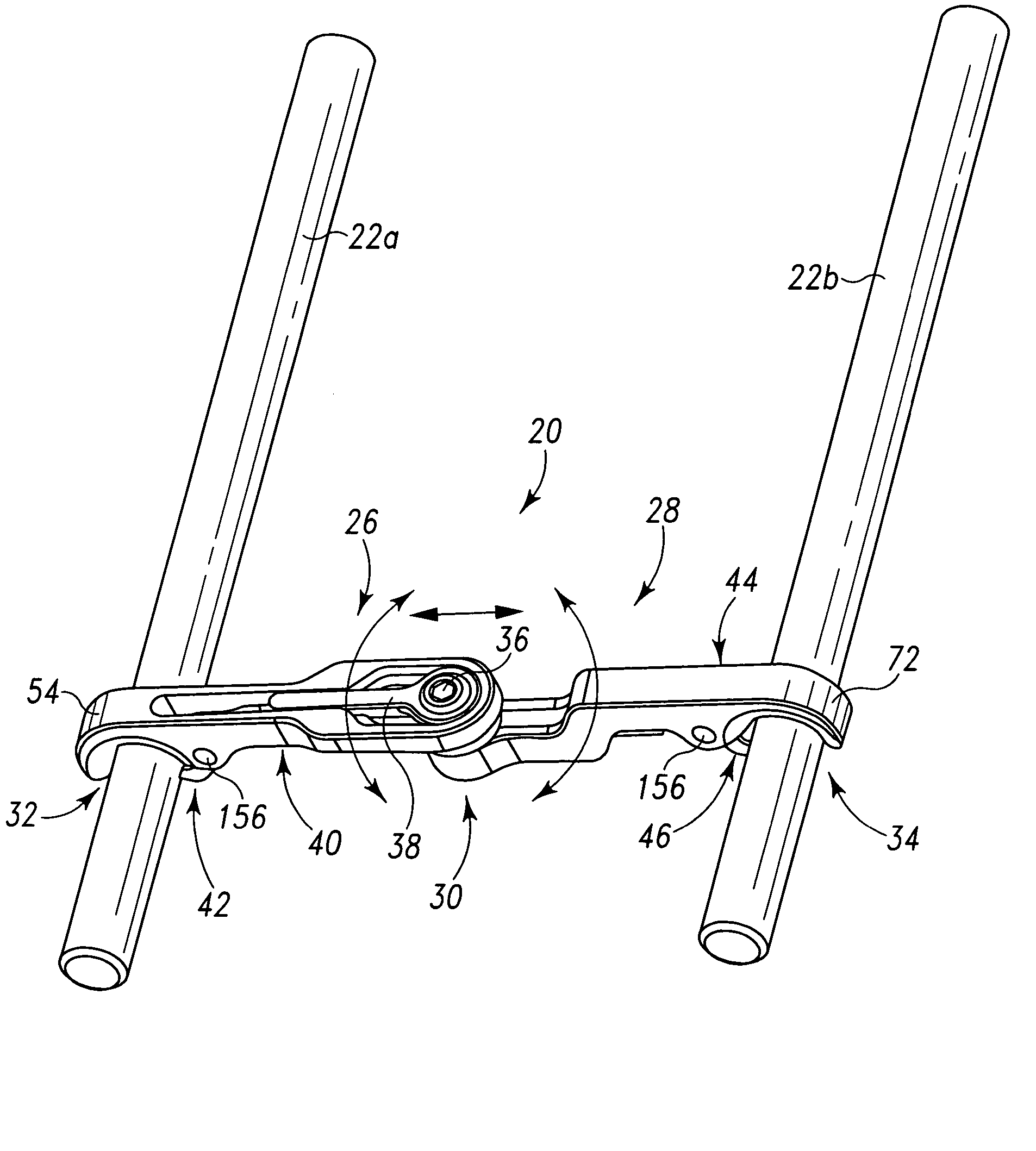
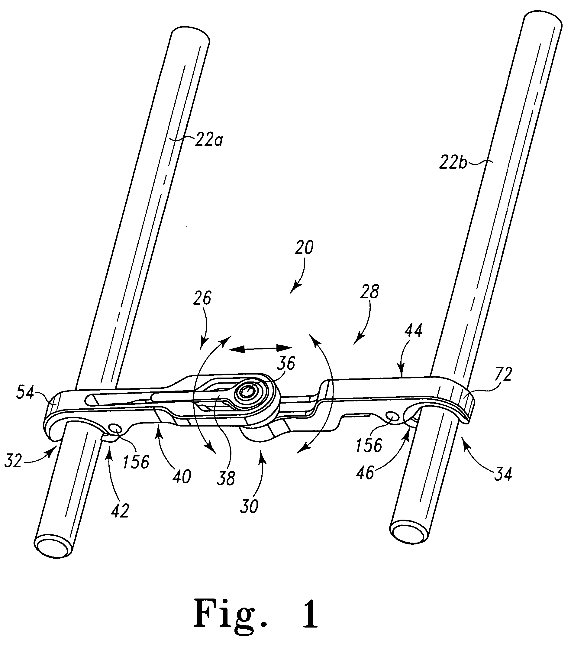
[0048] Referring to FIGS. 1-15 and particularly to FIG. 1, there is depicted an exemplary embodiment of a spinal cross-connector generally designated 20 fashioned in accordance with the principles of the present invention shown coupled / connected onto and between two spinal rods 22a and 22b (spinal fixation elements). The spinal rods 22a and 22b are representative of any type of straight or contoured spinal rod, or they can represent other spinal elements or members of a spinal fixation system. The cross-connector 20 is generally made from a biocompatible material such as titanium. Other biocompatible materials or compounds may be used.

[0049] The cross-connector 20 has a first connection member 26 and a second connection member 28 attached to one another at a pivot junction 30. The first connection member 26 includes a first clamping structure 32 on one end thereof for clamping onto a spinal rod (shown in FIG. 1 as spinal rod 22a). The second connection member 28 includes a second c...


PUM


Abstract

A multi-axial spinal cross-connector is configured for connection between spinal fixation devices such as spinal fixation rods. The cross-connector has first and second connection members that are joinable at a fixable pivot junction. The pivot junction allows the connection members to assume various positions relative to one another. A clamp is provided on each end of the first and second connection members whose open and closed states are controlled by fixation of a pivot structure which also fixates the positions of the first and second connection members relative to each other. The cross-connector provides single and/or multi-step locking of both end clamps at the pivot joint. The cross-connector also provides easy in situ sizing, positioning and adjustability.

Description

RELATED APPLICATIONS [0001] This patent application claims the benefit of and / or priority to U.S. Provisional Patent Application Ser. No. 60 / 849,230 filed Oct. 4, 2006, entitled “Multi-Axial Spinal Cross-Connectors” the entire contents of which is specifically incorporated herein by reference.BACKGROUND OF THE INVENTION [0002] 1. Field of the Invention [0003] The present invention relates to spinal fixation devices and, in particular, to cross-connectors for connecting spinal fixation devices, such as spinal rods that are attached onto a patient's spine. [0004] 2. Background Information [0005] There are many medical situations, because of disease, injury or deformity, where it is necessary to align and / or fix a desired relationship between adjacent vertebral bodies. In order to accomplish this goal, orthopedic spinal surgeons utilize spinal fixation devices to provide the desired relationship between adjacent vertebral bodies. Such spinal fixation devices typically include a spinal ...

Claims


Application Information

Patent Timeline
Patent Type & Authority Applications(United States)
IPC IPC(8): A61B17/58A61B17/08
CPCA61B17/7052
Inventor BUTLER, MICHAEL S.MILELLA, MICHAEL J. JR.BUCCI, KARA A.
Owner LIFE SPINE INC
Why Eureka
Try Eureka