
Generator stator bar quick-form tooling system and method

Inactive Publication Date: 2008-04-17
GENERAL ELECTRIC CO
View PDF4 Cites 1 Cited by
  • Summary
  • Abstract
  • Description
  • Claims
  • Application Information

AI Technical Summary

Benefits of technology

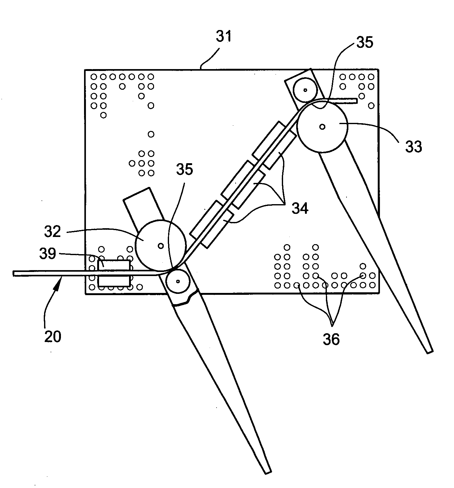
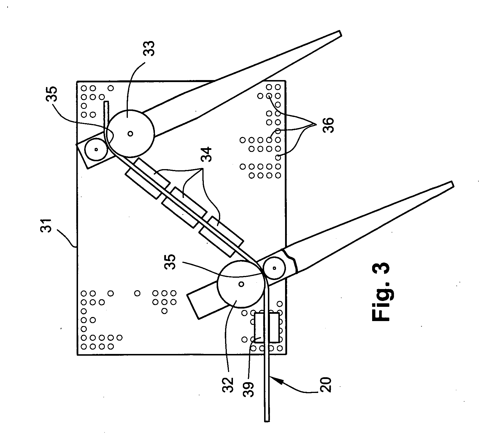
[0003]An example non-limiting implementation of a metal tooling form set-up method and modular tooling “quick-form” system and apparatus for shaping large electrical power generator stator bars is disclosed. The example implementation described herein includes a stator bar center section support structure / clamping station and a pair of stator bar end-arm support structures positioned at opposite sides of the center-section support structure. The stator bar end-arm support structures each have a support surface formed with an array of tool location alignment holes enabling a variety of diverse tooling modules, such as bend-forming, mid-curvature forming and adjustable clamping tools, to be precisely positioned relative to each other and to the center clamping station structure so as to produce desired bends in a piece of stator bar stock.
[0006]The provision of a modular stator bar bending form system and apparatus that comprises one or more support structures each having a surface replete with an array of tool position mounting holes that accept a variety of modular clamping, curvature-imparting and bend-forming tools, each arranged to define a portion of a stator bar's shape during the forming process, makes the process of setting-up differently configured bending forms for custom bar shaping applications both quick and easy. In addition, the exemplary quick-form tooling system and method implementation disclosed herein allows a desired stator bar bending form configuration to be rapidly and inexpensively duplicated at multiple and remote manufacturing / repair facilities.
[0007]As will be seen from the following description, the non-limiting example implementation of a stator bar quick-form tooling system and method presented herein provides numerous advantages over conventional prior art stator bar forming methods and apparatus. Such advantages include, for example, a modular tooling system and process that may be easily implemented and replicated by multiple generator manufacturing / repair centers, the ability to minimize tooling configuration set-up times for changes in production runs, and the versatility of using discrete modular tooling form set-ups and inserts which allow stator bar manufacturers to quickly configure and set-up a specific tooling form arrangement and begin first-piece qualification within a few hours time. For example, in most situations the design and manufacture of new tooling can be accomplished in as little as a few days, with tooling form set-up and first-piece forming taking only about eight hours. Another beneficial aspect of the disclosed example quick-form tooling system and method implementation is that it greatly reduces the amount of time and expense required to design and create new stator bar forms and also reduces the amount of variation in results produced from different generator manufacturing / repair centers when making the same stator bar.

Problems solved by technology

Currently, the manufacture of custom stator bars used in large electrical power generators is costly and time-consuming.
The fabrication and setting-up of bending forms is a time-consuming and costly undertaking, especially when forms are fabricated for custom or non-standard stator bar designs that may result in only a single use or have limited applications.

Method used


Image

  • Generator stator bar quick-form tooling system and method
  • Generator stator bar quick-form tooling system and method
  • Generator stator bar quick-form tooling system and method

Examples


Embodiment Construction

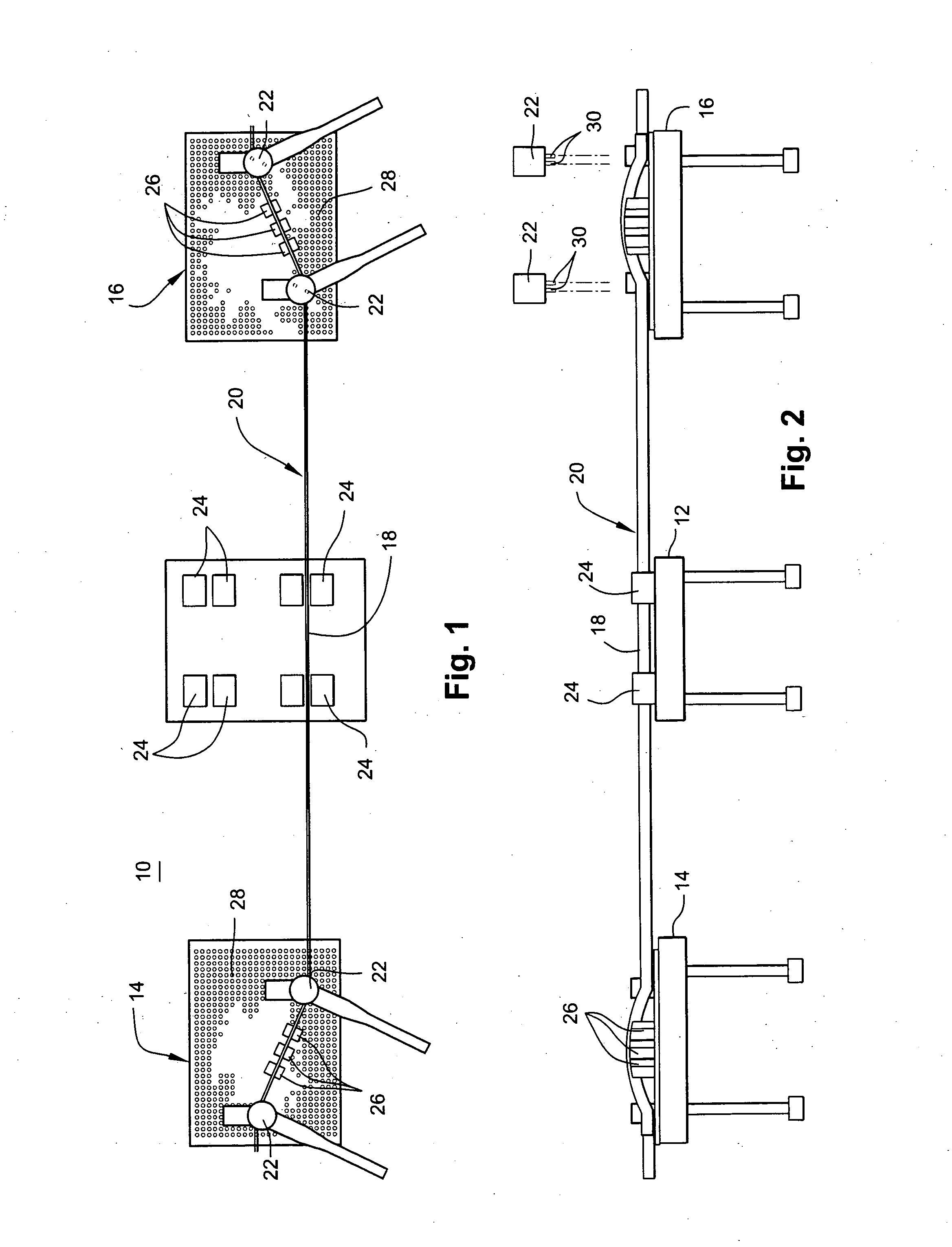
[0017]FIGS. 1 and 2 show an example arrangement of a quick-form tooling system 10 with stator bar tooling module bending apparatus in a simplified, schematic form. FIG. 1 provides a schematic top view and FIG. 2 provides a schematic side view. A center stator bar clamping table or support structure 12 may be anchored to the floor in any suitable fashion. On either side of center clamping table 12, one or more stator bar end-arm support structures, 14 and 16 respectively, are also provided.

[0018]In the example implementation disclosed herein, each of the support structures is fashioned in the form of a table having a flat top and several support legs and may be initially moveable or repositionable, but during use are anchored to the floor in accordance with conventional practice. It can be appreciated from FIGS. 1 and 2 that the center clamping / support table structure 12 both supports and immobilizes a center section 18 of a piece of conventional stator bar stock 20. Mounted on the t...


PUM

PropertyMeasurementUnit
Heightaaaaaaaaaa

Abstract

A modular “quick-form” tooling system and stator bar form set-up method is provided for reconfigurably mounting various stator bar bending / forming tool modules that are used to produce custom bends and curvatures in a length of stator bar stock. At least one stator bar support structure is provided having a support surface formed with an array of tool location alignment holes that allow a variety of different bend-forming tooling modules to be positioned relative to each other in a manner that will define the shape of a generator stator bar during a bending / forming process.

Description

FIELD OF THE INVENTION[0001]This invention relates generally to metal tooling equipment and, more specifically, to metal tooling forms and bend-forming tools used to shape generator stator bars.BACKGROUND OF THE INVENTION[0002]Currently, the manufacture of custom stator bars used in large electrical power generators is costly and time-consuming. This is particularly true in field repair situations where a needed stator bar configuration is not of standard design, or at least is not of a design that is familiar to the repairing entity. In such instances, new replacement stator bars are manufactured using custom fabricated stator bar bending forms based upon existing stator bar design drawings, if available, or from actual stator bars removed from a generator and shipped to the manufacturing / repair facility. The fabrication and setting-up of bending forms is a time-consuming and costly undertaking, especially when forms are fabricated for custom or non-standard stator bar designs that...

Claims


Application Information

Patent Timeline
IPC IPC(8): H05K13/04
CPCH02K15/0414Y10T29/5313Y10T29/53143Y10T29/49009Y10T29/53161Y10T29/49073
Inventor CLOUGH, MARKHENLEY, JAMES T.HENKEL, JEFFERY A.
Owner GENERAL ELECTRIC CO
Learn More