Magnetic resonance apparatus

Active Publication Date: 2008-04-17
TOSHIBA MEDICAL SYST CORP
View PDF7 Cites 8 Cited by
  • Summary
  • Abstract
  • Description
  • Claims
  • Application Information

AI Technical Summary

Benefits of technology

[0009]Under these circumstances, it has been required to make the passive

Problems solved by technology

In the above-mentioned prior art technique, the main magnetic field is corrected by the gradient magnetic field, and hence the correction amount and the corre

Method used


Image

  • Magnetic resonance apparatus
  • Magnetic resonance apparatus
  • Magnetic resonance apparatus

Examples


Example

[0019]An embodiment of the present invention will be described below with reference to the accompanying drawings.

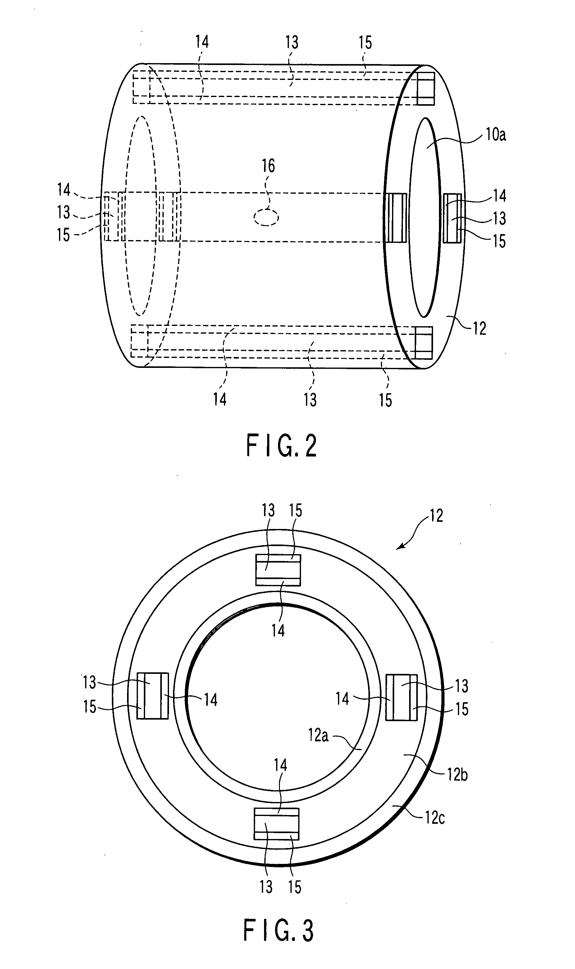
[0020]FIG. 1 is a schematic view of a part of a magnetic resonance imaging (MRI) apparatus 100 according to the embodiment of the present invention.

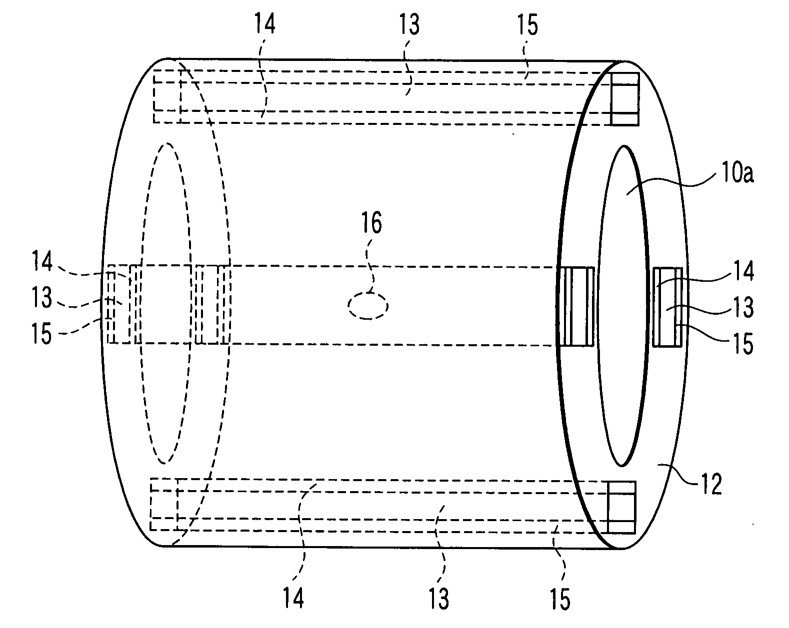
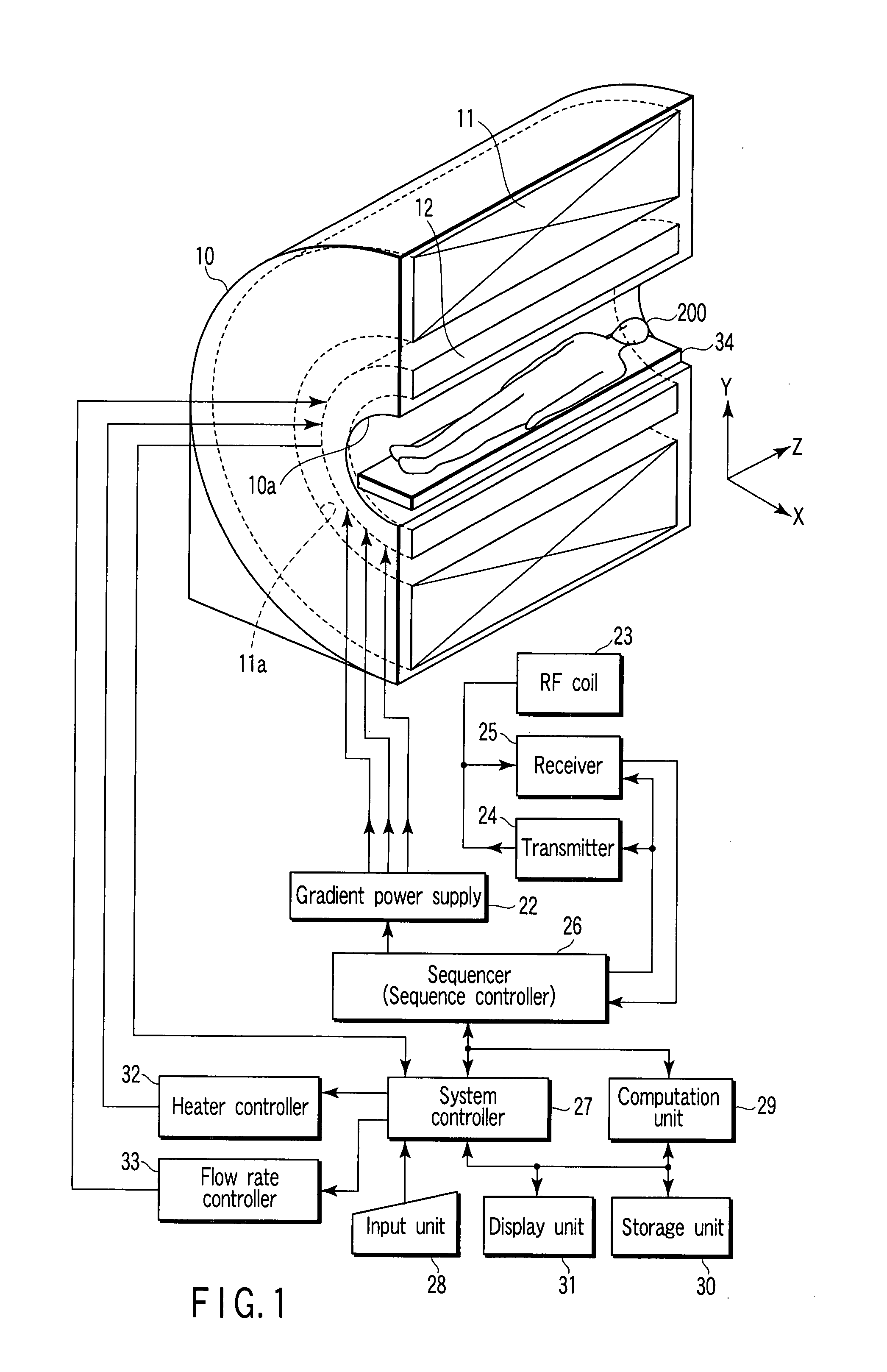
[0021]The MRI apparatus 100 of this embodiment comprises a gantry 10, a magnet 11, a gradient coil unit 12, a gradient power supply 22, a radio frequency coil (RF coil) 23, a transmitter 24, a receiver 25, a sequencer 26, a system controller 27, an input unit 28, an computation unit 29, a storage unit 30, a display unit 31, a heater controller 32, and a flow rate controller 33. In addition, the MRI apparatus 100 includes a bed (not shown) which is disposed adjacent to the gantry 10. The gantry 10 is typically formed in such a manner that a substantially cylindrical imaging space 10a is formed in the center thereof so as to allow the space 10a to penetrate the gantry 10. The axial direction of the imaging space 10a is defined a...


PUM


Abstract

A magnetic resonance apparatus in which magnetic metal pieces are accommodated in an accommodation section so as to correct uniformity in a main magnetic field, includes an acquisition unit which acquires temperature information related to at least one of a temperature of the magnetic metal pieces accommodated in the accommodation section, a temperature of the accommodation section, and a temperature of a position in the vicinity of the accommodation section, and a temperature adjustment unit which adjusts the temperature of the magnetic metal pieces to a target temperature by preheating the magnetic metal pieces on the basis of the temperature information acquired by the acquisition unit.

Description

CROSS-REFERENCE TO RELATED APPLICATIONS[0001]This application is based upon and claims the benefit of priority from prior Japanese Patent Application No. 2006-280515, filed Oct. 13, 2006, the entire contents of which are incorporated herein by reference.BACKGROUND OF THE INVENTION[0002]1. Field of the Invention[0003]The present invention relates to a magnetic resonance apparatus in which a magnetic metal part is accommodated in an accommodation section for correction of uniformity in a main magnetic field.[0004]2. Description of the Related Art[0005]A magnetic resonance apparatus is provided with a magnet (a permanent magnet or an electromagnet) for generating a main magnetic field and a gradient magnetic field system (a gradient coil) for generating a gradient magnetic field. The main magnetic field is a static magnetic field and should desirably have high uniformity. In order to maintain the uniformity of the main magnetic field, shimming is performed. Shimming is roughly classifi...

Claims


Application Information

Patent Timeline
IPC IPC(8): G01R33/3873
CPCG01R33/3873G01R33/3804
Inventor NAKABAYASHI, KAZUTOHANAWA, MASATOSHI
Owner TOSHIBA MEDICAL SYST CORP
Why Eureka
Try Eureka