System and method for testing the electromagnetic susceptibility of an electronic display unit

Inactive Publication Date: 2008-04-17
AMBER PRECISION INSTUMENTS
View PDF3 Cites 24 Cited by
  • Summary
  • Abstract
  • Description
  • Claims
  • Application Information

AI Technical Summary

Problems solved by technology

An error in the electronic display unit caused by the EM noise is detected using an e

Method used


Image

  • System and method for testing the electromagnetic susceptibility of an electronic display unit
  • System and method for testing the electromagnetic susceptibility of an electronic display unit
  • System and method for testing the electromagnetic susceptibility of an electronic display unit

Examples


Embodiment Construction

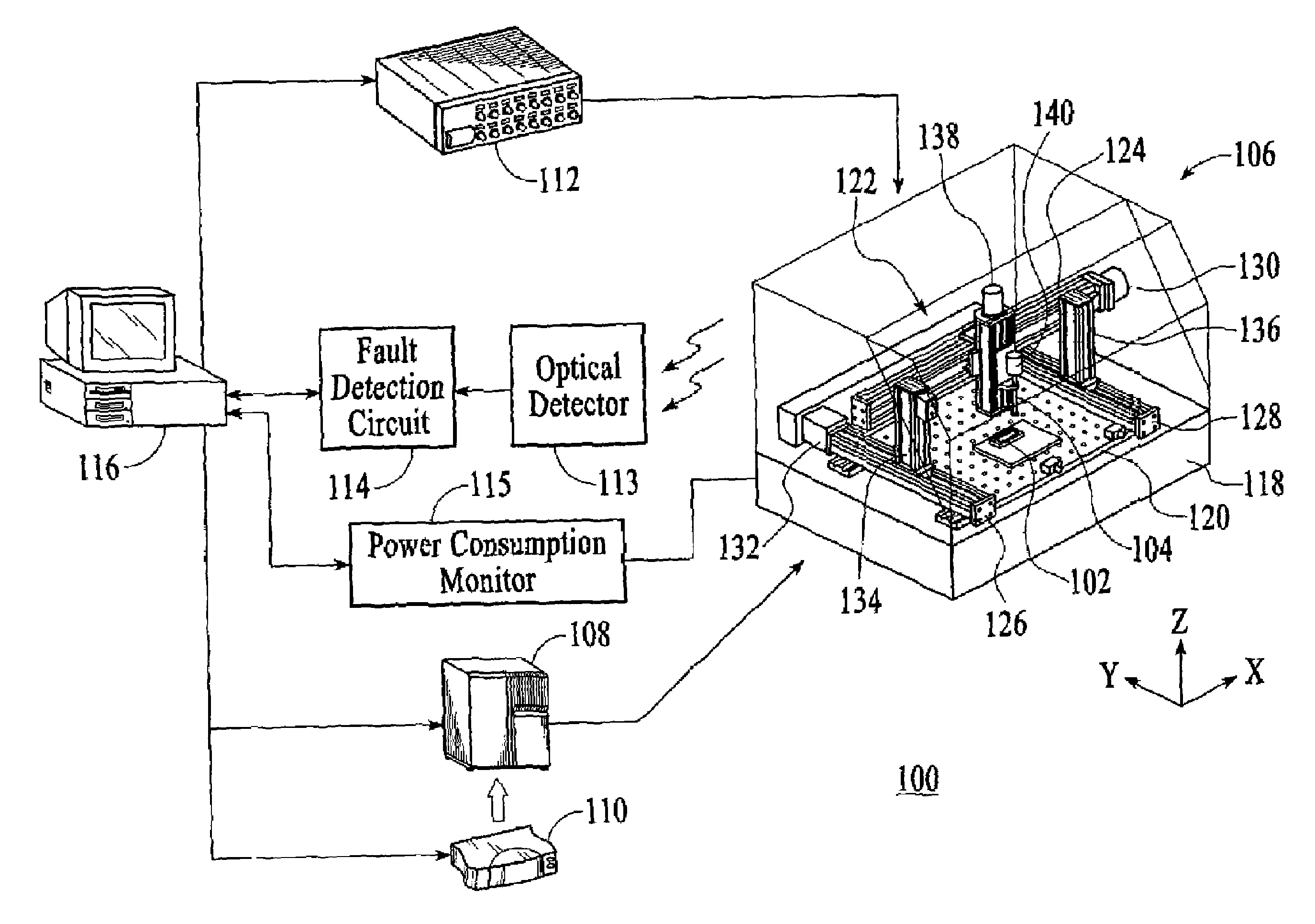
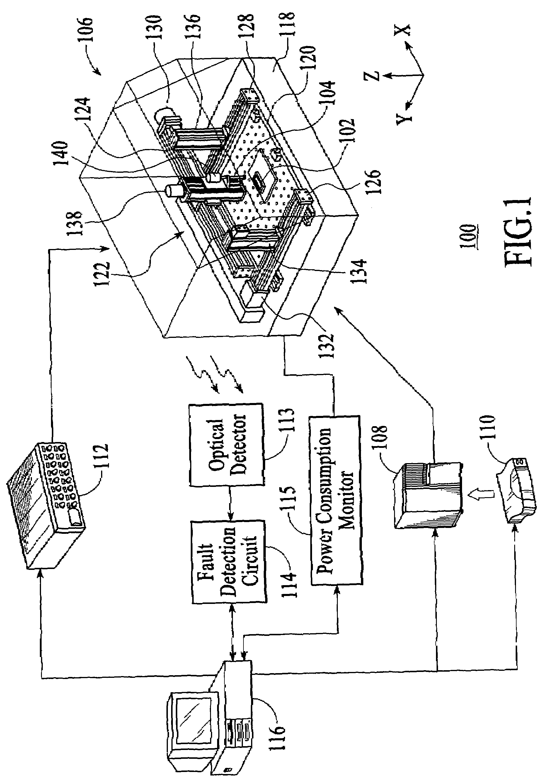
[0014]With reference to FIG. 1, a system 100 for testing the electromagnetic (EM) susceptibility of an electronic flat panel display unit 102, which is the equipment under test (EUT), in accordance with an embodiment of the invention is described. The EUT 102 can be any type of a flat panel display, such as a plasma display unit, a liquid crystal display (LCD) unit or an organic light-emitting diode (OLED) display unit. The EM testing system 100 is designed to subject the EUT 102 to EM noise at various testing locations of the EUT to extract EM susceptibility information to determine vulnerable areas of the EUT with respect to EM noise. The EM susceptibility information may be used to produce an EM susceptibility map of the EUT 102. The EM susceptibility map can then be used to address the EM vulnerable areas of the EUT 102 to reduce the EM susceptibility of the EUT. Thus, using the EM testing system 100, electronic flat panel display units with improved performance can be produced....


PUM


Abstract

A system and method for testing the electromagnetic (EM) susceptibility of an electronic display unit monitors the light emitted from the electronic display unit as EM noise is applied at a particular testing location of the electronic display unit. An error in the electronic display unit caused by the EM noise is detected using an electrical signal generated in response to the light from the electronic display unit.

Description

BACKGROUND OF THE INVENTION[0001]Sophisticated electronic flat panel display units, such as plasma display units, liquid crystal display (LCD) units and organic light-emitting diode (OLED) display units, are susceptible to electromagnetic (EM) disturbances, such as electrostatic discharge (ESD). ESD can cause both hard errors and soft errors in electronic display units. ESD-related hard-errors in electronic display units are errors caused by physical damage of one or more electronic components of the electronic display units, while ESD-related soft errors are errors caused by incorrect signals or data in the electronic display units. ESD-related soft errors in electronic display units include bit errors, upsets, unwanted resets etc.[0002]Currently, there are no viable tools to locate specific areas of an electronic flat panel display unit that are susceptible to EM disturbances, such as ESD. However, electronic flat panel display units are routinely tested for ESD immunity to determ...

Claims


Application Information

Patent Timeline
IPC IPC(8): G01R31/00
CPCG01R31/002G09G2330/06G09G3/006
Inventor POMMERENKE, DAVID J.
Owner AMBER PRECISION INSTUMENTS
Why Eureka
Try Eureka