Integrated electronic circuitry comprising tunable resonator
a technology of integrated electronic circuitry and resonators, which is applied in the direction of impedence networks, single resonant circuits with varying inductance/capacitance only, continuous tuning, etc., can solve the problems of additional losses, difficult integration with other electronics circuitry in the same, and difficult tuning of filters based on such resonators. achieve the effect of easy integration in a semiconductor substra
- Summary
- Abstract
- Description
- Claims
- Application Information
AI Technical Summary
Benefits of technology
Problems solved by technology
Method used
Image
Examples
first embodiment
[0055]FIG. 3A illustrates a first embodiment showing a simplified resonance circuit which comprises, in parallel with a resonator BAW 31, a negative capacity Cneg 32.
[0056] Surprisingly, it has been noticed that one may obtain the same result than the one obtained with one inductor in the known circuit simply by using an active circuit which has the behavior of a negative capacity Cneg.
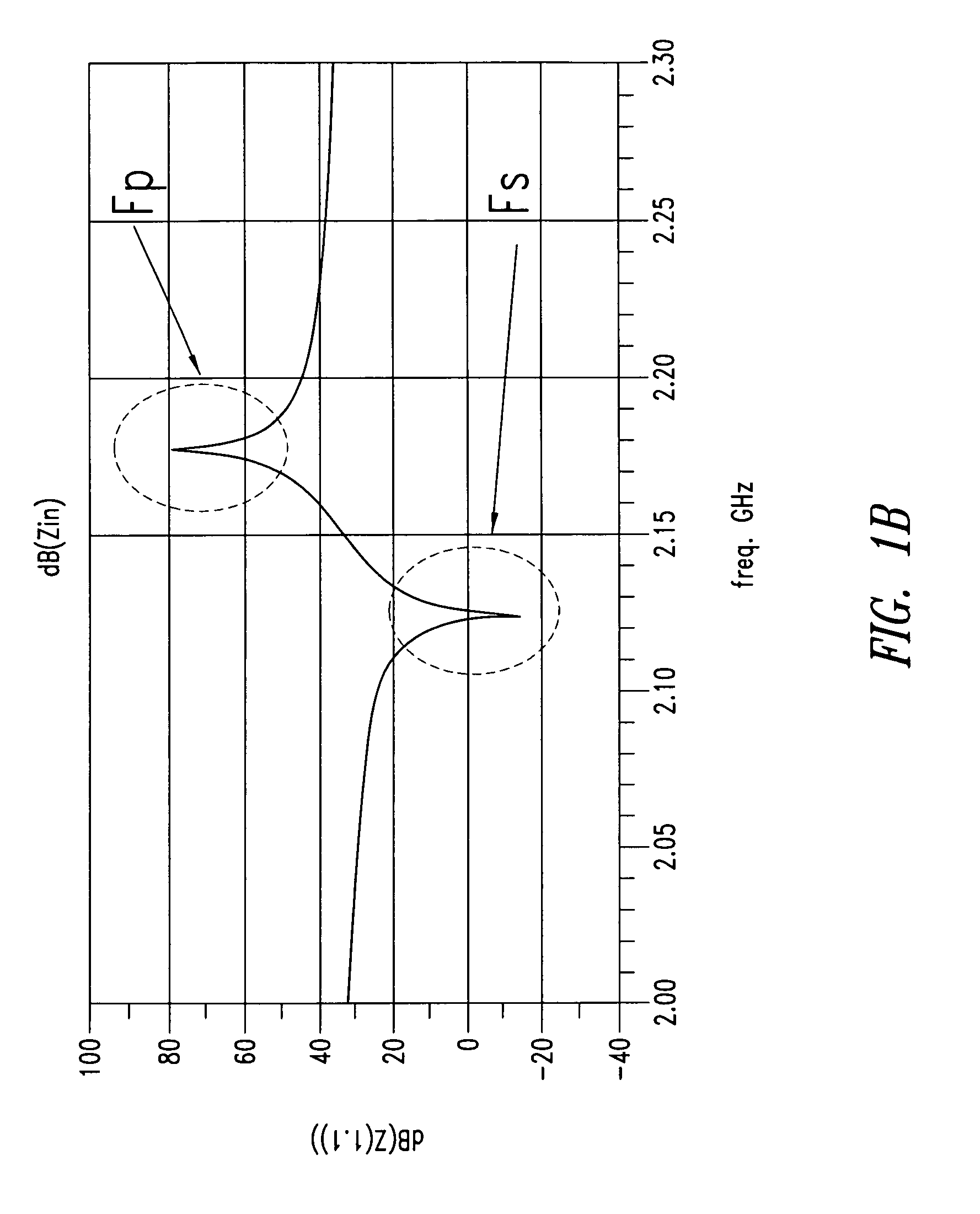
[0057] Simulations have shown indeed that, as a function of the absolute value of this negative capacity, one may cause the shifting, either to the right or to the left, of the anti-resonance frequency Fp while maintaining unchanged the series resonance frequency, as this is illustrated in FIGS. 3B and 3C.
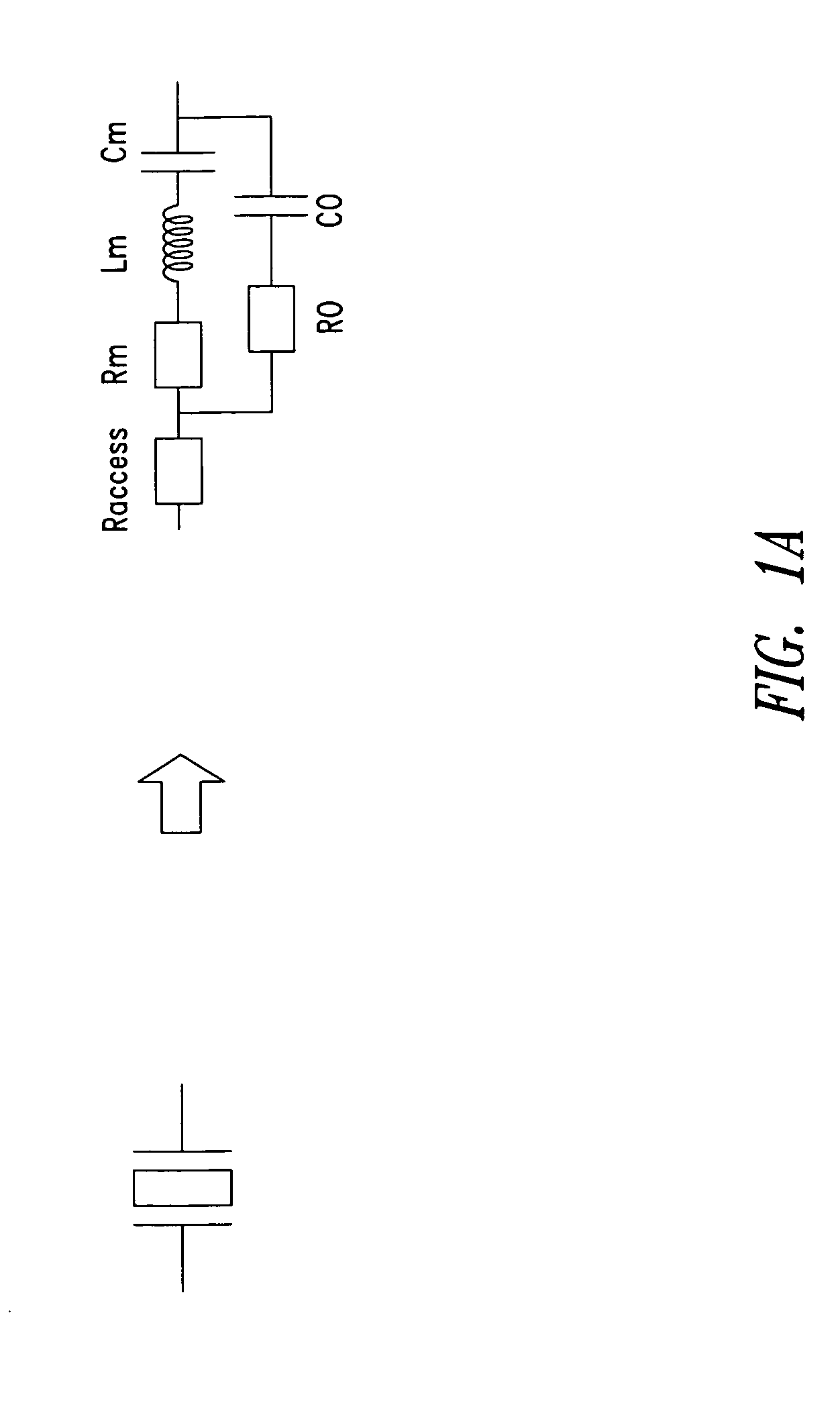
[0058] More particularly, FIG. 3B shows that when the absolute value of Cneg is lower than the internal parameters C0+Cm of the BAW resonator, then the anti-resonance frequency is shifted to the right.
[0059] Conversely, when the absolute value of Cneg is higher than C0+Cm, the anti-resonance frequ...
second embodiment
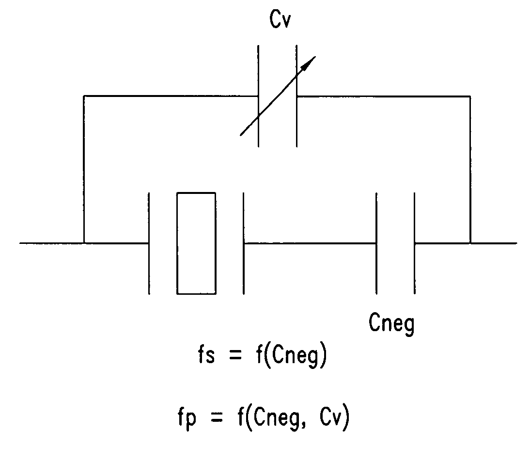
[0061]FIG. 4A illustrates a tunable resonator circuit which comprises, in series with the circuit of FIG. 3A, a tunable capacity component, such as a varactor for instance having a variable capacity Cv.
[0062] One thus obtains a circuit which provides numerous possibilities of tunings in accordance to the value of Cneg.
[0063]FIGS. 4B to 4D respectively illustrate the characteristics curves of the second embodiment in accordance with the negative capacity Cneg with respect to the values C0+Cm and C0+Cm+Cv.
[0064] When the absolute value of Cneg is lower than C0+Cm, then one notices the shifting to the right of the two series and parallel resonance frequencies, as this is illustrated in FIG. 4B.
[0065] When the absolute value of Cneg is higher than C0+Cm+Cv, the series resonance frequency Fs and the parallel resonance frequency Fp are both shifted to the left, as illustrated in FIG. 4C.
[0066] At last, when the absolute value of Cneg is comprised within C0+Cm and C0+CM+Cv, one notice ...
third embodiment
[0068]FIG. 5A illustrates a third embodiment which comprises a negative capacity Cv coupled in series with the BAW resonator. As this is seen in FIG. 5B and 5C, one can shift, respectively to the rights or to the left, the series resonance frequency. Thus, when the absolute value of Cneg is lower than C0+Cm, the negative capacity causes the shifting to the right of the series resonance frequency, as this is illustrated in FIG. 5B. Conversely, when the absolute value of Cneg is higher than C0+Cm, one observes the shifting to the left of the series resonance frequency, as this is shown in FIG. 5C.
PUM
 Abstract
Description
Claims
Application Information
 - R&D
- Intellectual Property
- Life Sciences
- Materials
- Tech Scout
- Unparalleled Data Quality
- Higher Quality Content
- 60% Fewer Hallucinations
Browse by: Latest US Patents, China's latest patents, Technical Efficacy Thesaurus, Application Domain, Technology Topic, Popular Technical Reports.
© 2025 PatSnap. All rights reserved.Legal|Privacy policy|Modern Slavery Act Transparency Statement|Sitemap|About US| Contact US: help@patsnap.com


