Method for driving display panel

a display panel and display panel technology, applied in the direction of instruments, static indicating devices, etc., can solve the problems of reducing users are restricted to viewing the display panel, and users cannot observe the brightness of different frames, so as to enhance the viewing angle of the display panel and enhance the display quality of the display panel

Inactive Publication Date: 2008-04-17
AU OPTRONICS CORP
View PDF7 Cites 22 Cited by
  • Summary
  • Abstract
  • Description
  • Claims
  • Application Information

AI Technical Summary

Benefits of technology

[0010]The present invention is to provide a method for driving a display panel. The display panel has a plurality of unit pixels to display the frames. The display of these unit pixels is controlled by a plurality of switches. The method of the present invention is to transmit a plurality of gate signals. These gate signals can drive these switches, and to transmit a plurality of data signals to these switches. Further, it can provide a plurality of pixels voltages to these unit pixels, and generate the potential differences with the common voltages of the unit pixels. As a result, these unit pixels are controlled to display in the group time. The data signals corresponding to these unit pixels are the brightness signals corresponding to different gammas, and can enhance the viewing angle of the display panel. Besides, the total amount of the potential differences of each unit pixel under the group time is substantially equal to zero. Therefore, the residual image doesn't results in the display panel while viewing frames and the display quality of the display panel is enhanced. More, the group time includes a plurality of driving unit times. At least one group of pixels displays in each the driving unit time.

Problems solved by technology

As a result, users are restricted to view the display panel.
Further, by a fast change between two frames, users cannot observe that these frames have different brightness.
However, the residual image results in the display panel while viewing frames.
The display quality of the display panel is decreased, and causes a bad visual feeling while viewing the display panel.

Method used


Image

  • Method for driving display panel
  • Method for driving display panel
  • Method for driving display panel

Examples


Embodiment Construction

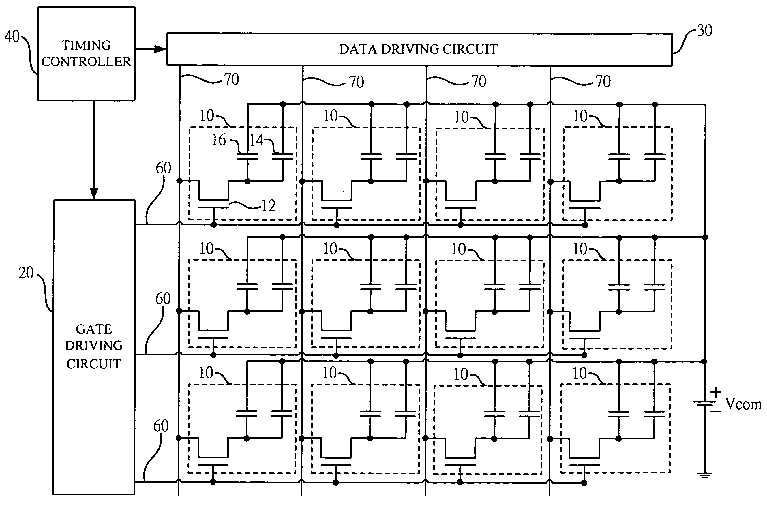
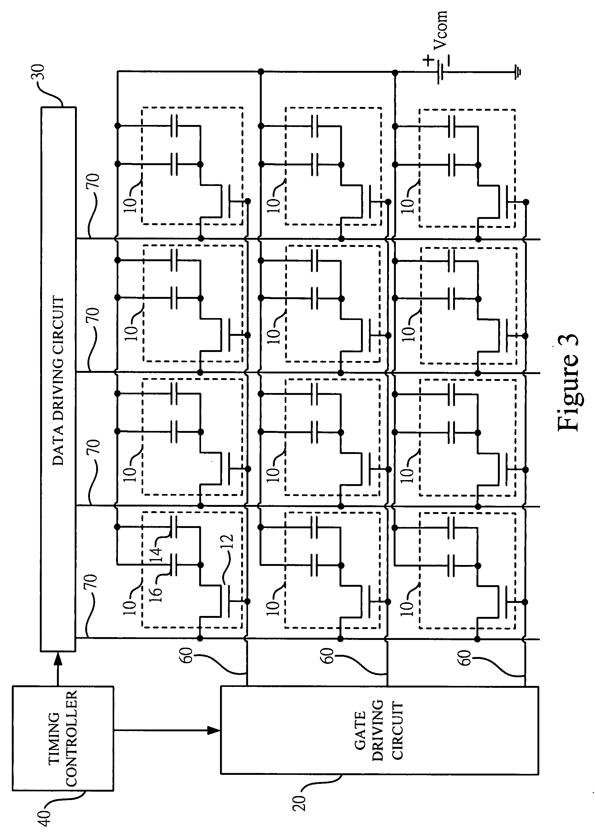
[0039]First, refer to FIG. 3. FIG. 3 is one of the preferred embodiments in the present invention showing a circuit diagram. As shown in the figure, the display panel of the present invention comprises a plurality of unit pixels 10, a gate driving circuit 20, a data driving circuit 30, a timing controller 40, and a common voltage source Vcom. The gate driving circuit 20 is coupled with a plurality of gate lines 60, and the data driving circuit 30 is coupled with a plurality of data lines 70. These gate lines 60 are arranged (or layout) in rows, and these data lines 70 are arranged (or layout) in columns and also substantially interlaced with these gate lines 60 to form the unit pixels 10. The unit pixels 10 comprise a frame. Each unit pixel 10 comprises a switch 12, a storage capacitor 14, and a liquid crystal capacitor 16. The switch 12 is used to control the unit pixels 10 for display. The switch 12 can be a transistor (such as thin film transistor, for example, bottom gate type, ...


PUM


Abstract

Disclosed is a method for driving a display panel. The display panel includes a plurality of unit pixels and a plurality of switches. The switches are used for controlling the unit pixels to display. The method includes transmitting a plurality of gate signals to the switches for driving the switches. More, the driving method also includes transmitting a plurality of data signals to the switches for providing a plurality of pixel voltages to the unit pixels and providing common voltages to the unit pixels as well as generating the potential differences with the common voltage and the pixel voltages of the unit pixels for controlling the display of the unit pixels by a group time. The total amount of potential differences in each unit pixel in the group time is substantially equal to zero. The group time includes a plurality of driving unit times. In each driving unit time, at least one group of pixels displays. A group of pixels includes a plurality of grayscale levels of brightness. The total brightness of the grayscale levels accords with a predetermined brightness. Therefore, the display not only can increase its viewing angel, but also can avoid residual image caused from residual charge.

Description

BACKGROUND OF THE INVENTION[0001]1. Field of the Invention[0002]The present invention relates to a driving method and, more particularly, to a method for driving a display panel.[0003]2. Description of the Prior Art[0004]According to current development of flat panel display (FPD) technology, different FPD manufacturers are continuously developing different kinds of display panels, such as liquid crystal display (LCD), plasma display panel (PDP), and organic light emitting diode (OLED). In the current display panels, no matter the display is twisted nematic-LCD (TN-LCD), multi-domains vertical alignment-LCD (MVA-LCD), or in-plane switch-LCD (IPS-LCD), users will find color distortion phenomenon while viewing frames in large viewing angel. The reason is that the alignment angle of the liquid crystal causes changes of brightness and gamma curve in the large viewing angle. Therefore, the color through large viewing angel is different from the color through centering angle while users v...

Claims


Application Information

Patent Timeline
Patent Type & Authority Applications(United States)
IPC IPC(8): G09G3/36
CPCG09G3/3614G09G3/3648G09G3/3655G09G2320/0673G09G2320/0204G09G2320/0257G09G2320/028G09G2300/0447
Inventor LAI, MING-SHENGCHIANG, MIN-FENGKUO, CHING-TINGHUANG, HSUEH-YING
Owner AU OPTRONICS CORP
Why Eureka
Try Eureka