Advanced automatic digital radiographic hot light method and apparatus

a technology of automatic digital radiographic and hot light, applied in the field of radiographic image details, can solve the problems of no help in visualizing too, no contrast enhancement in the area, and difficulty in achieving the effect of improving the image quality improving detail visualization, and increasing the contrast of the selected region of interes

Inactive Publication Date: 2008-04-17
CARESTREAM HEALTH INC
View PDF19 Cites 11 Cited by
  • Summary
  • Abstract
  • Description
  • Claims
  • Application Information

AI Technical Summary

Benefits of technology

[0006]According to the present invention, there is provided an improved method for automatically modifying the processing and rendering of a digital radiographic image.
[0014]The invention has some advantages. For example, the context of the original image is maintained by operating only on the selected region of interest, the remainder of the image is unchanged. In addition, the image quality of the selected region of interest is improved over traditional window and level adjustment, because the contrast of the selected region of interest is increased without incurring quantization due to the toe and shoulder of the tone scale look-up table application. The region of interest can be processed by trend removal and / or spatial frequency processing to aid the user in visualizing details and texture that are ordinarily masked. The region of interest can be transformed with a color palette to additionally improve detail visualization. The region of interest can be displayed magnified or in its true size to improve visualization of the ROI image. The ROI overlay(s) can be stored along with the original image so that they can be used for future reference, perhaps identifying key findings within an image.

Problems solved by technology

However, the hot light is of no help in visualizing too light areas and there is no contrast enhancement in the area of interest.
This process requires skill and is time consuming and can result in sub-optimal rendering of the rest of the image.

Method used


Image

  • Advanced automatic digital radiographic hot light method and apparatus
  • Advanced automatic digital radiographic hot light method and apparatus
  • Advanced automatic digital radiographic hot light method and apparatus

Examples


Embodiment Construction

[0020]In general, the present invention automatically provides an improved rendering of a user selected region of interest of a displayed digital (radiographic) image. Regions of the image that have been rendered too dark or too light are remapped to pixel values that are well rendered by the tone scale look-up table. While the visibility of the region of interest is improved, no loss of visual context is suffered because the rendering of the overall image remains the same.

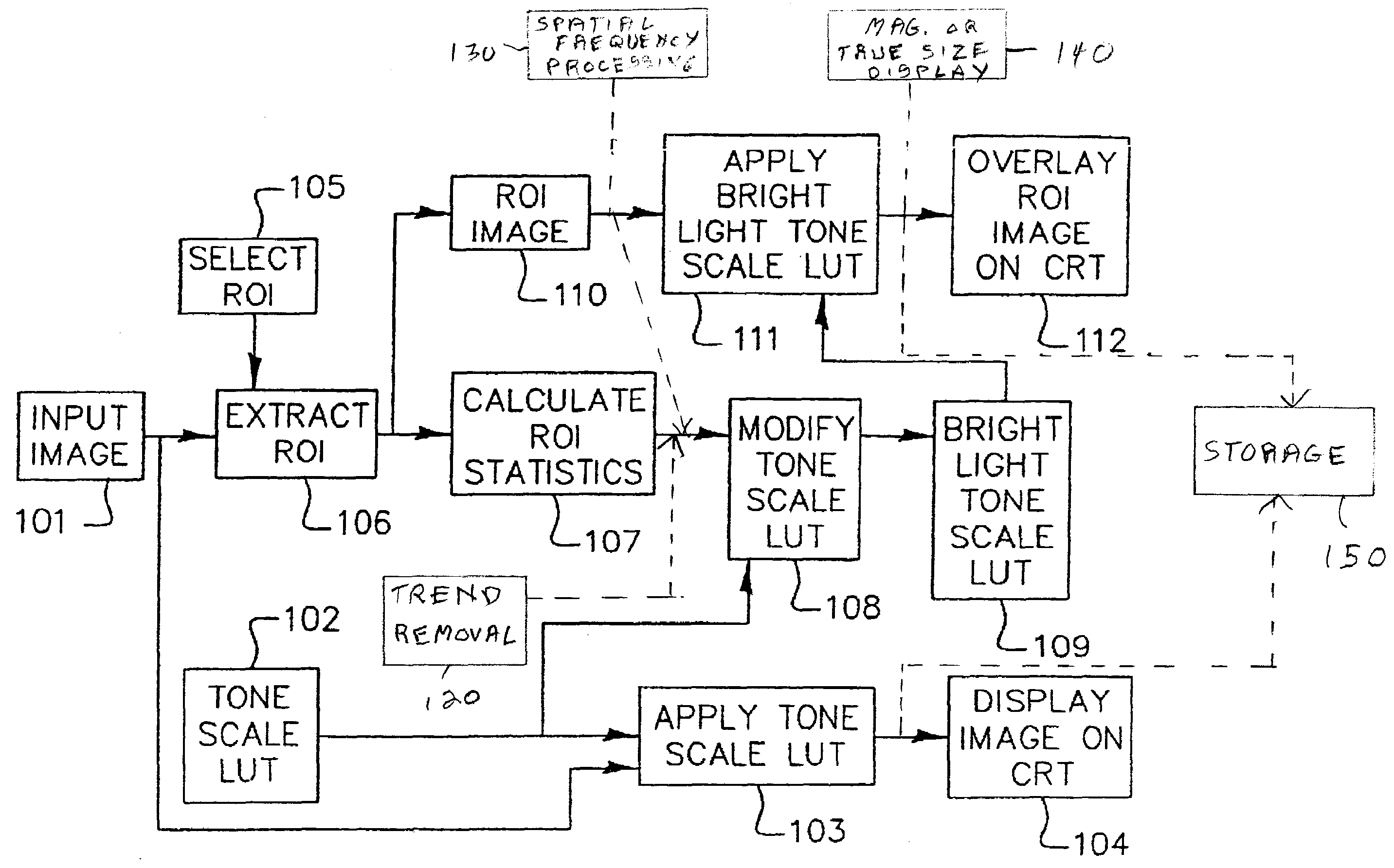
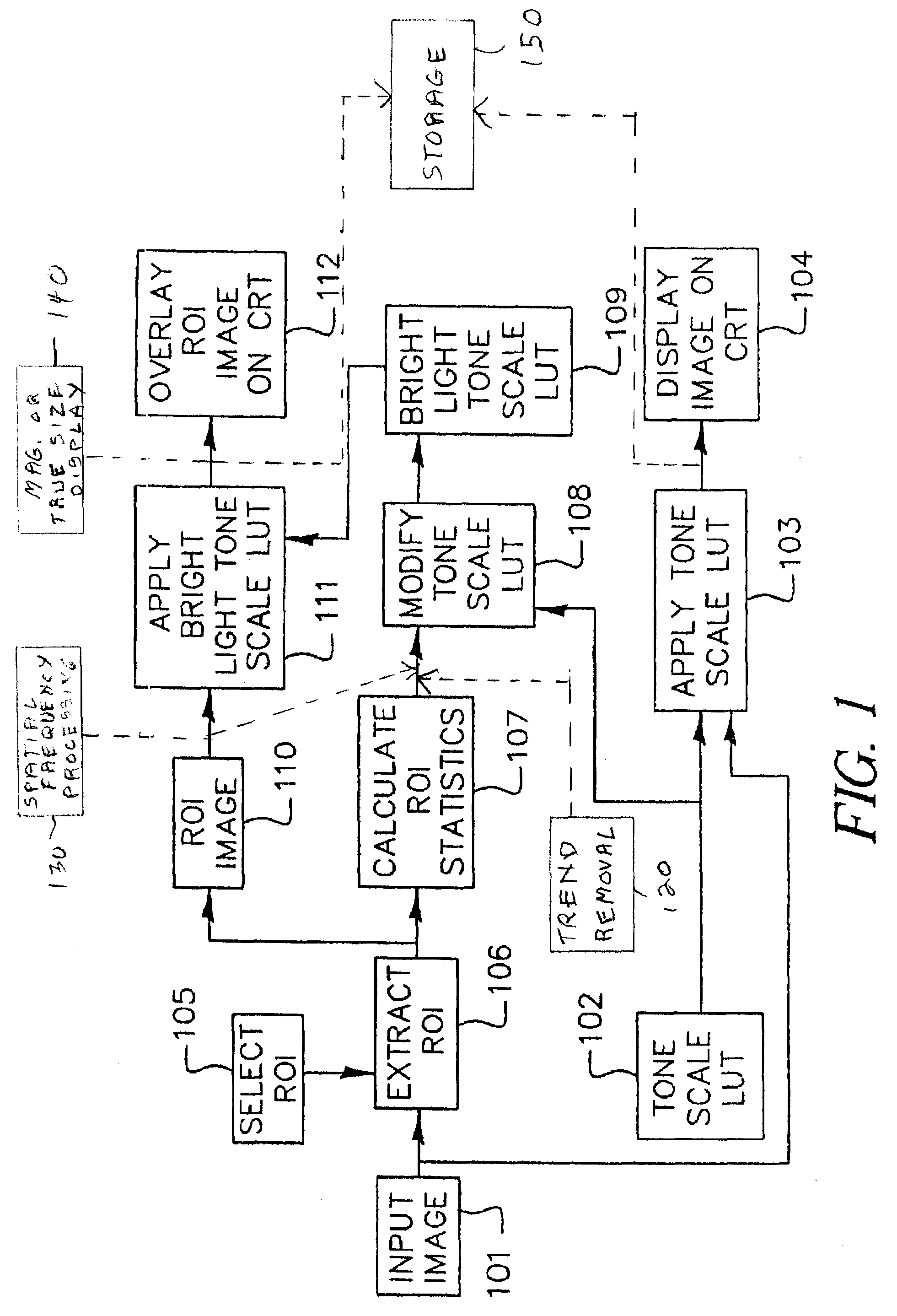
[0021]An environment for the present invention is shown in FIG. 1. A digital radiographic image 101 of digital code values is selected for viewing. The digital radiographic image can be generated by computed radiography (CR) or direct digital radiography (DR) or by digitizing radiographic film. A tone scale (LUT) look-up table 102 is provided which is a default tone scale rendering to best visualize the entire dynamic range of the input image 101. Although the creation of the tone scale LUT 102 is outside of the s...


PUM


Abstract

A method for automatically modifying the rendering of an image based on an analysis of pixel values within a selected region of interest. The method includes: providing a digital input image of digital pixel values and tone scale look-up table (LUT); creating a default rendered image by applying the tone scale lookup table to the input image; displaying the default rendered image; selecting a region of interest from the input image; computing the histogram of the pixel values within the region of interest; creating a bright light image by remapping the pixel values within the region of interest based on an analysis of the histogram and the tone scale table; wherein the tone scale lookup table has been adjusted by one or more of increasing or decreasing the overall contrast, and of reversing the polarity of the tone scale LUT; and overlaying the bright light image on default rendered image.

Description

FIELD OF THE INVENTION[0001]This invention relates in general to image enhancement in digital image processing and more particularly to the enhanced rendering of selected regions of interest to improve the visual presentation of image details, specifically radiographic image details.BACKGROUND OF THE INVENTION[0002]Digital medical imaging has become increasingly important in medical imaging practice and has increased productivity for health care professionals who need to utilize images as part of patient care. It is desirable that a user be able to rapidly extract diagnostically useful information from medical images and that any user interaction with the image display be rapid, intuitive and as automated as possible.[0003]One source of medical images is the detection of x-rays projected through a region of interest of a patient so as to measure the x-ray transmittance with an imaging detector such as used in computed radiography and direct digital radiography. Because the digital r...

Claims


Application Information

Patent Timeline
Patent Type & Authority Applications(United States)
IPC IPC(8): G06K9/40
CPCG06T5/008G06T2207/30004G06T2207/10116G06T5/40
Inventor HEATH, MICHAEL D.SEHNERT, WILLIAM J.
Owner CARESTREAM HEALTH INC
Why Eureka
Try Eureka