Mirror image pair sanding blocks

a technology of mirror image and sanding block, which is applied in the direction of gear teeth, manufacturing tools, manufacturing apparatuses for gear teeth, etc., to achieve the effect of facilitating adheren

a technology of mirror image and sanding block, which is applied in the direction of gear teeth, manufacturing tools, manufacturing apparatuses for gear teeth, etc., to achieve the effect of facilitating adheren

US20080090496A1Inactive Publication Date: 2008-04-17SANTUCCI GERARD

Image

  • Mirror image pair sanding blocks
  • Mirror image pair sanding blocks
  • Mirror image pair sanding blocks

Examples


Embodiment Construction

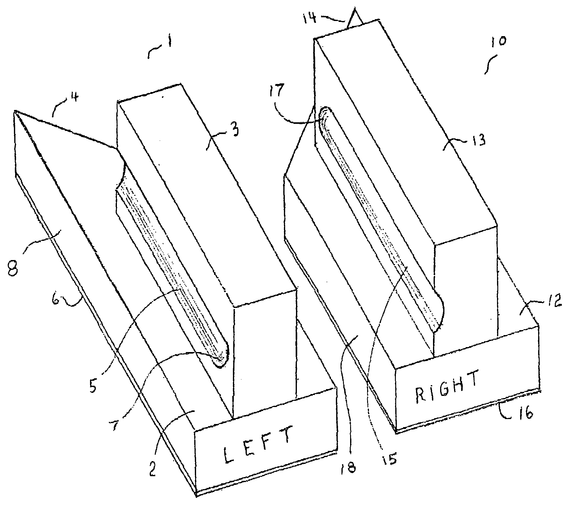
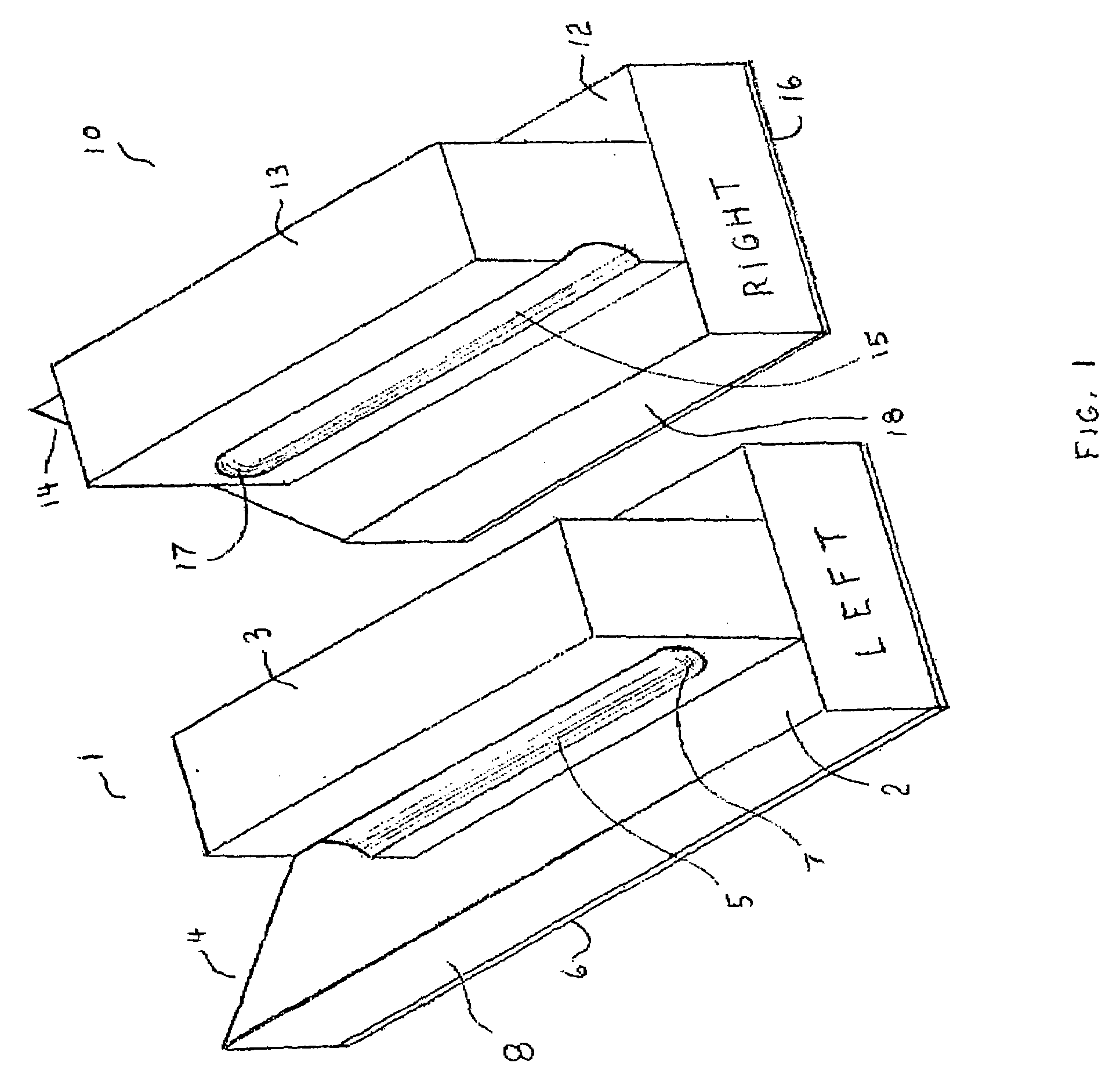
[0040]FIG. 1 shows the mirror image pair of sanding blocks of this invention, block 1 for the left hand and block 10 for the right hand. Block 1 has base 2 with front sloping end 4 and grasp handle 3. Box cove channel 5 on the long side 8 of base 2 has stop 7 at the rear for the third, fourth or fifth finger tip. The user's field conditions and other work variables dictate to the user which finger engages the rear stop 7. Any fingers rearward of a finger engaging rear stop 7 are tucked inward toward the palm of the user's hand, as in making a fist with the user's hand.

[0041]The abrasive surface 6 is at the bottom of base 2. Block 10, has base 12 with front sloping end 14, and grasp handle 13. Box cove channel 15 on the short side 18 of base 12 has stop 17 at the front for the thumb. Abrasive surface 16 is on the bottom of base 12.

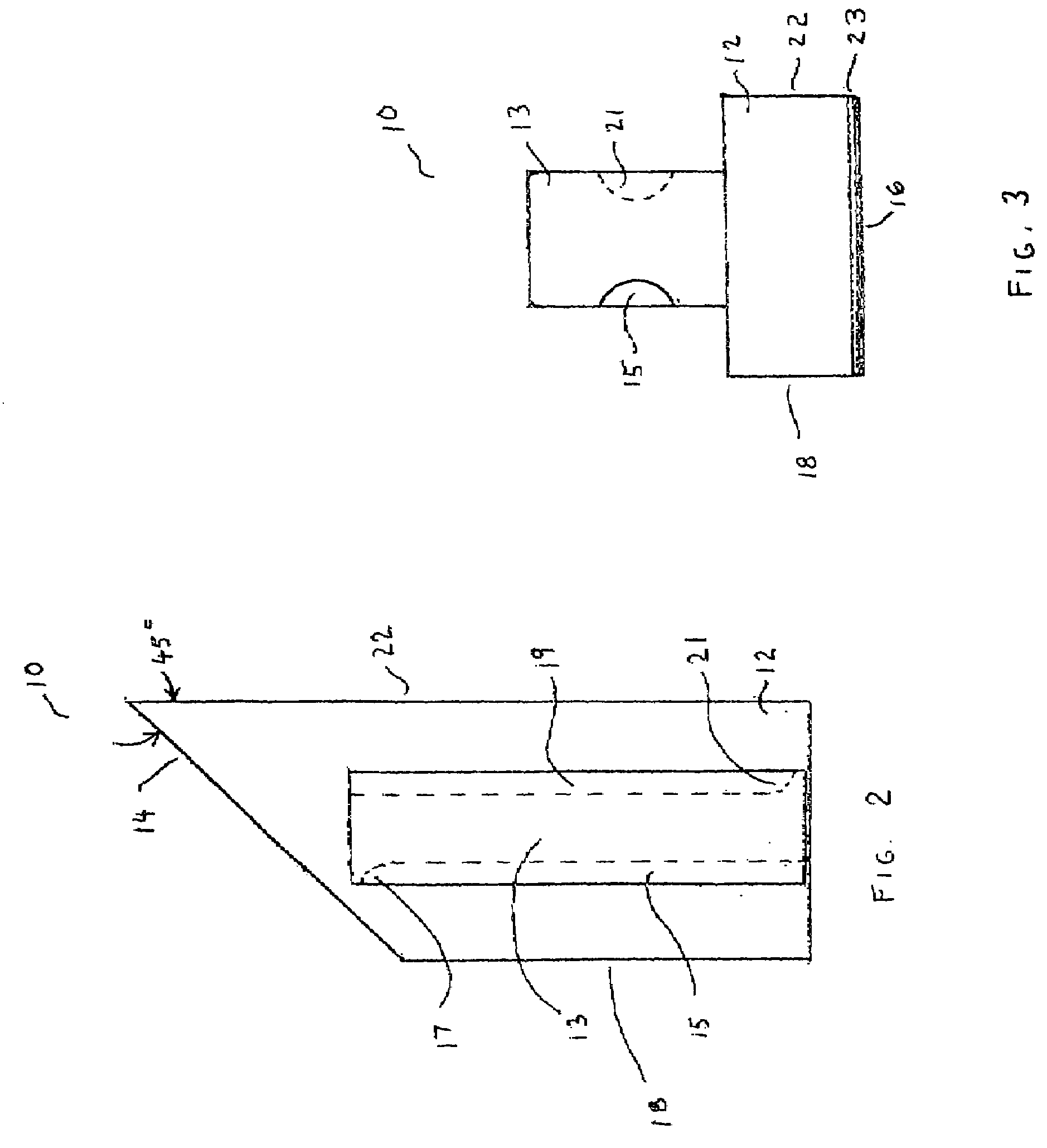
[0042]FIGS. 2 and 3 are top and end views respectively of right handed block 10 for right hand use. Block 1 would be an identical mirror image. Here box co...


PUM

PropertyMeasurementUnit
Angleaaaaaaaaaa
Angleaaaaaaaaaa
Massaaaaaaaaaa

Abstract

A right handed or left handed sanding block can be provided individually or as a mirror image pair. Each block includes a grasp handle and a fastening surface engaging a replaceable sanding pad. Each handle includes a pair of cove box channels to fit the fingers of the user. These channels have forward and rear finger stops located at opposite sides. The channel positions are mirror image reversed for the right hand and left hand blocks. The forward stop provides a rest for the thumb and the front vertical surface provides a rest for the index finger. A rear finger stop provides a rest for a tip of another finger. The block is a truncated rectangle with an offset edge. The short side of the block provides a safety harbor clearance when the other hand of the user grasps the work piece.

Description

FIELD OF THE INVENTION[0001]The present invention relates to a mirror image pair sanding blocks which provide ease of grasping by either the left hand or the right hand, while providing other-hand clearance during manual grasping a workpiece.BACKGROUND OF THE INVENTION[0002]The prior art reveals a variety of sanding blocks. A sampling of such prior art includes U.S. Pat. No. 6,267,658 of Ali which shows a rectangular sanding block base with a raised channeled handle oriented diagonally relative to the base; the handle is symmetric with respect to right hand or left hand use. U.S. Pat. No. 5,313,746 of Zarriello, U.S. Pat. No. 5,718,622 of Jones, and U.S. Pat. No. 5,533,926 of Nemazi reveal sanding blocks with triangular shapes and symmetric pointed fronts. All of these patents show sanding blocks which are symmetric with respect to the left or right side of the pad. The sanding block of U.S. Pat. No. 5,054,248 of Thayer shows an asymmetric body molded of a flexible cellular polyuret...

Claims


Application Information

Patent Timeline
17 Apr 2008
Publication
US20080090496A1
IPC
B24B1/00; B24D15/00
CPC
B24D15/02
Inventors
SANTUCCI, GERARD