
Method for calibrating sensor positions in a human movement measurement and analysis system

a human movement measurement and analysis system technology, applied in the direction of sensors, gyroscopes/turn-sensitive devices, speed measurement using gyroscopic effects, etc., to achieve the effect of minimizing the error of anatomical joint gap

Inactive Publication Date: 2008-04-17
UNIVERSITY OF NEW BRUNSWICK
View PDF10 Cites 55 Cited by
  • Summary
  • Abstract
  • Description
  • Claims
  • Application Information

AI Technical Summary

Benefits of technology

[0033] refining the transformation matrices of the human body kinematic model to minimize anatomical joint gap error; and

Problems solved by technology

Given that we are currently limited to surface mounted technologies, we are forced to track the skeleton by inference, and as such, we use the surface mounted sensors to infer the underlying skeletal motions.

Method used


Image

  • Method for calibrating sensor positions in a human movement measurement and analysis system
  • Method for calibrating sensor positions in a human movement measurement and analysis system
  • Method for calibrating sensor positions in a human movement measurement and analysis system

Examples


Embodiment Construction

[0045] Generally speaking, the systems described herein are directed to methods for calibrating sensor positions in a human or animal movement measurement and analysis system. As required, embodiments of the present invention are disclosed herein. However, the disclosed embodiments are merely exemplary, and it should be understood that the invention may be embodied in many various and alternative forms. The Figures are not to scale and some features may be exaggerated or minimized to show details of particular elements while related elements may have been eliminated to prevent obscuring novel aspects. Therefore, specific structural and functional details disclosed herein are not to be interpreted as limiting but merely as a basis for the claims and as a representative basis for teaching one skilled in the art to variously employ the present invention. For purposes of teaching and not limitation, the illustrated embodiments are directed to methods for calibrating sensor positions in ...


PUM


Abstract

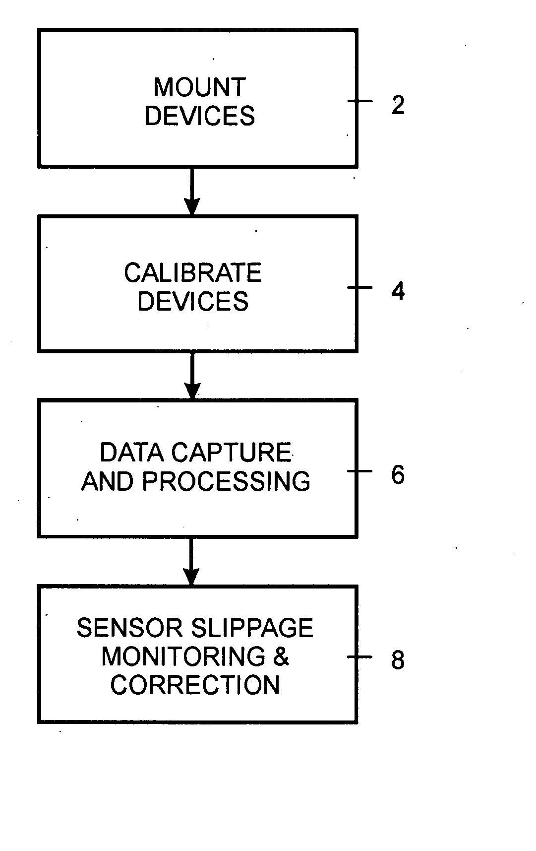
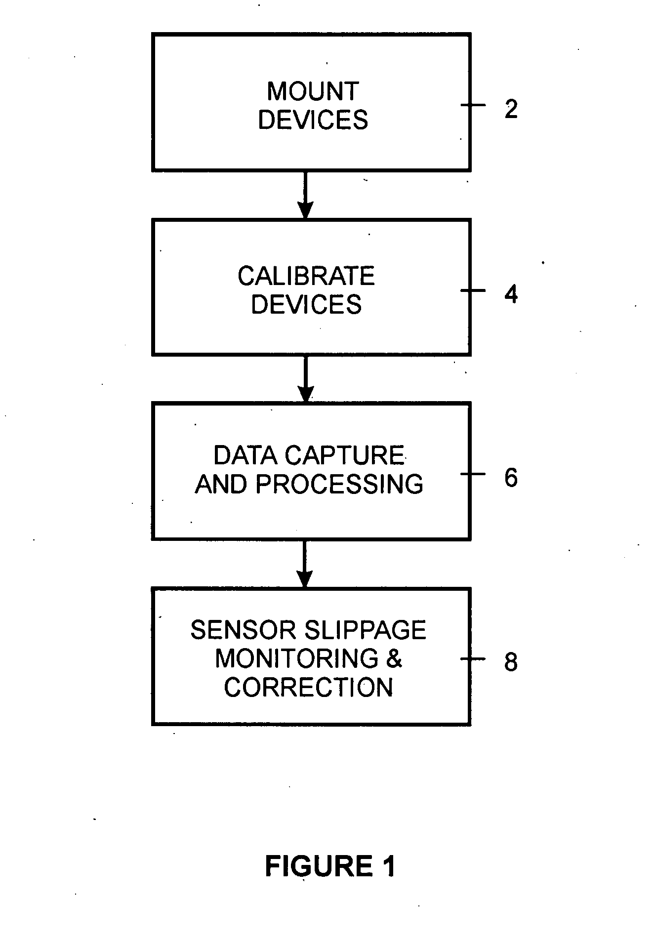
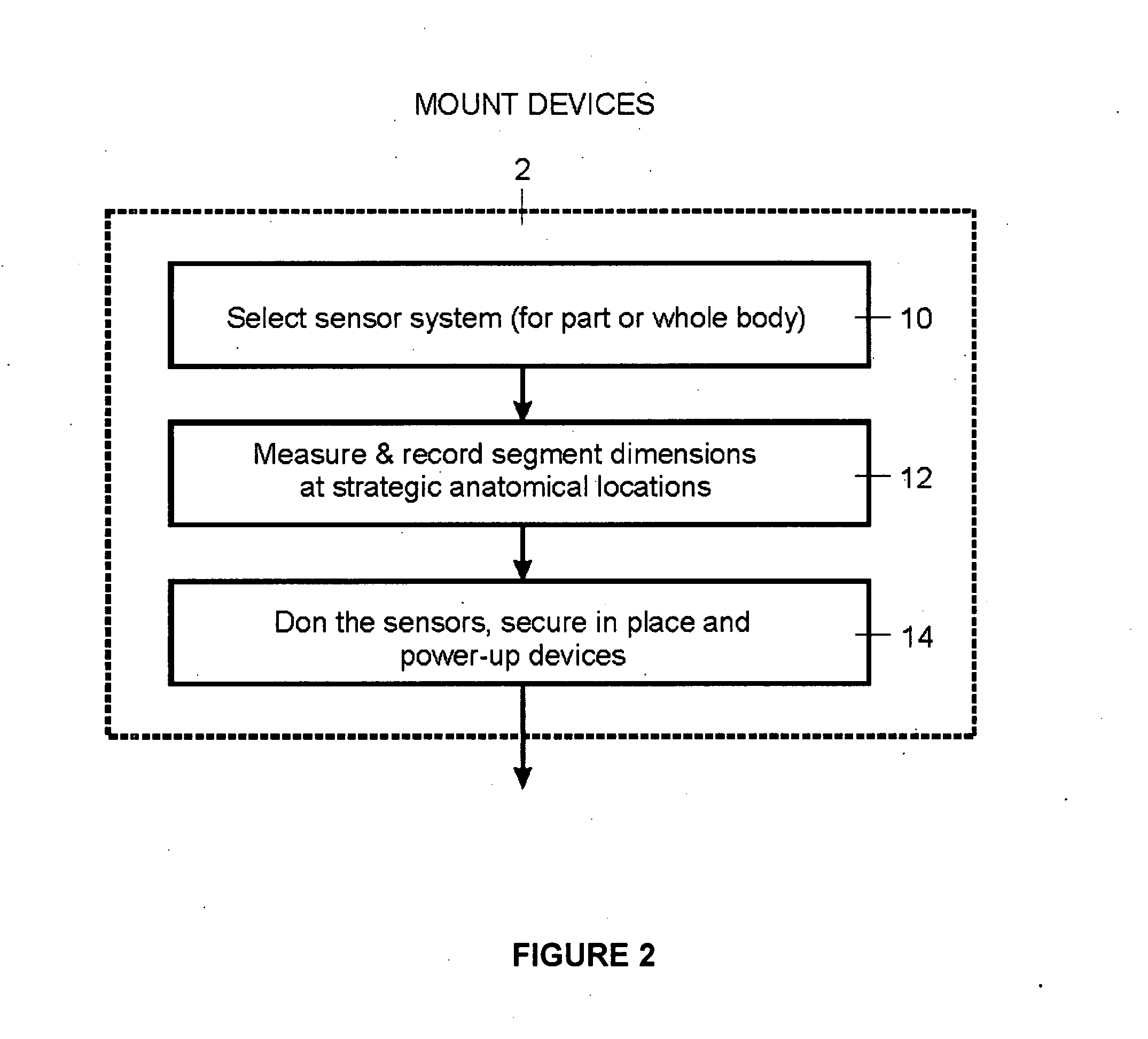
A method for calibrating the position and orientation of a 6-DOF sensor system mounted on a multi-segmented structure, such as the human body, is provided. The method includes a stage for mounting the sensors on the body, a stage for acquiring the 6-DOF kinematics from those sensors, a calibration stage whereby the prior stages are used to determining the sensor-to-segment transformations that are most physiologically optimal during relative skeletal motions, and a stage that to periodically monitor and correct for sensor slippage.

Description

CROSS REFERENCE TO RELATED U.S PATENT APPLICATIONS [0001] This patent application relates to U.S. provisional patent application Ser. No. 60 / 834,158 filed on Jul. 31, 2006 entitled METHOD FOR CALIBRATING SENSOR POSITIONS IN A HUMAN MOVEMENT MEASUREMENT AND ANALYSIS SYSTEM, filed in English, which is incorporated herein in its entirety by reference.FIELD OF INVENTION [0002] The present invention relates generally to a method for determining the six fixed independent coordinates (3 displacements and 3 rotations) of body surface mounted motion sensors relative to the underlying skeletal frame, for the purpose of capturing six degree of freedom (6-DOF) kinematic and kinetic information of human skeletal motion, and for analyzing the information in an anatomically and physiologically meaningful way. BACKGROUND OF THE INVENTION [0003] Human movement analysis began formally at the end of the 19th century with the advent of cinematography, and its application to capturing animal motion by p...

Claims


Application Information

Patent Timeline
Patent Type & Authority Applications(United States)
IPC IPC(8): G06F19/00G01P21/00
CPCA61B5/1121A61B2560/0223A61B5/4528A61B5/1126
Inventor MCGIBBON, CHRISSEXTON, ANDREWKREBS, DAVID
Owner UNIVERSITY OF NEW BRUNSWICK
Learn More