Systems and methods using gravity and buoyancy for producing energy

a technology of energy production and buoyancy, applied in the direction of hydro energy generation, engine components, machines/engines, etc., can solve the problems of unbalanced condition of cylinders and drive the rotational member, and achieve the effect of facilitating smooth and reliable sliding motion, reducing the amount of cylinders, and sufficient buoyancy forces

Inactive Publication Date: 2008-04-24
PASSIVE ENERGY
View PDF29 Cites 17 Cited by
  • Summary
  • Abstract
  • Description
  • Claims
  • Application Information

AI Technical Summary

Benefits of technology

[0022] In one embodiment of the present invention, the expandable vessel preferably includes an expandable chamber having an upper chamber section and a lower chamber section that is telescopically receivable within the upper chamber section. The upper chamber section desirably has an internal volume that is larger than an internal volume of the lower chamber section. Although the present invention is not limited by any particular theory of operation, it is believed that providing an upper chamber having a larger volume than the lower chamber received therein, the vessel will produce sufficient buoyancy forces for moving the vessel upwardly after the vessel has been expanded.
[0023] In certain preferred embodiments of the present invention, the system may include a flexible diaphragm extending between the upper and lower chamber sections for forming an air-tight seal between the upper and lower chamber sections. The flexible diaphragm may be provided on the outside or the inside of the upper and lower chamber sections. In one embodiment, the diaphragm may be provided on both the outside and the inside of the upper and lower chamber sections. In one embodiment, an air-tight compartment may be formed between the upper and lower chamber sections by using any one of a broad range of flexible sealing materials including rubber, plastic, polymers, flexible sheets, etc. The upper and lower chamber sections are desirably coupled together by sliding brackets that enable the lower chamber section to be telescopically received within the upper chamber section. In one embodiment, the upper and lower chamber sections are coupled together using two sliding brackets. In other preferred embodiments, the upper and lower chamber sections may be coupled together using three, four, or more sliding brackets. The sliding brackets preferably facilitate smooth and reliable sliding motion between the upper and lower chamber sections.

Problems solved by technology

One problem with using water as an energy source, however is that the power plants must be located adjacent the supply of water.
The unbalanced condition of the cylinders drives the rotational member.

Method used


Image

  • Systems and methods using gravity and buoyancy for producing energy
  • Systems and methods using gravity and buoyancy for producing energy
  • Systems and methods using gravity and buoyancy for producing energy

Examples


Embodiment Construction

[0065] The headings used herein are for organizational purposes only and are not meant to be used to limit the scope of the description or the claims. As used throughout this application, the word “may” is used in a permissive sense (i.e., meaning having the potential to), rather than the mandatory sense (i.e., meaning must). Similarly, the words “include”, “including”, and “includes” mean including but not limited to. To facilitate understanding, like reference numerals have been used, where possible, to designate like elements common to the figures.

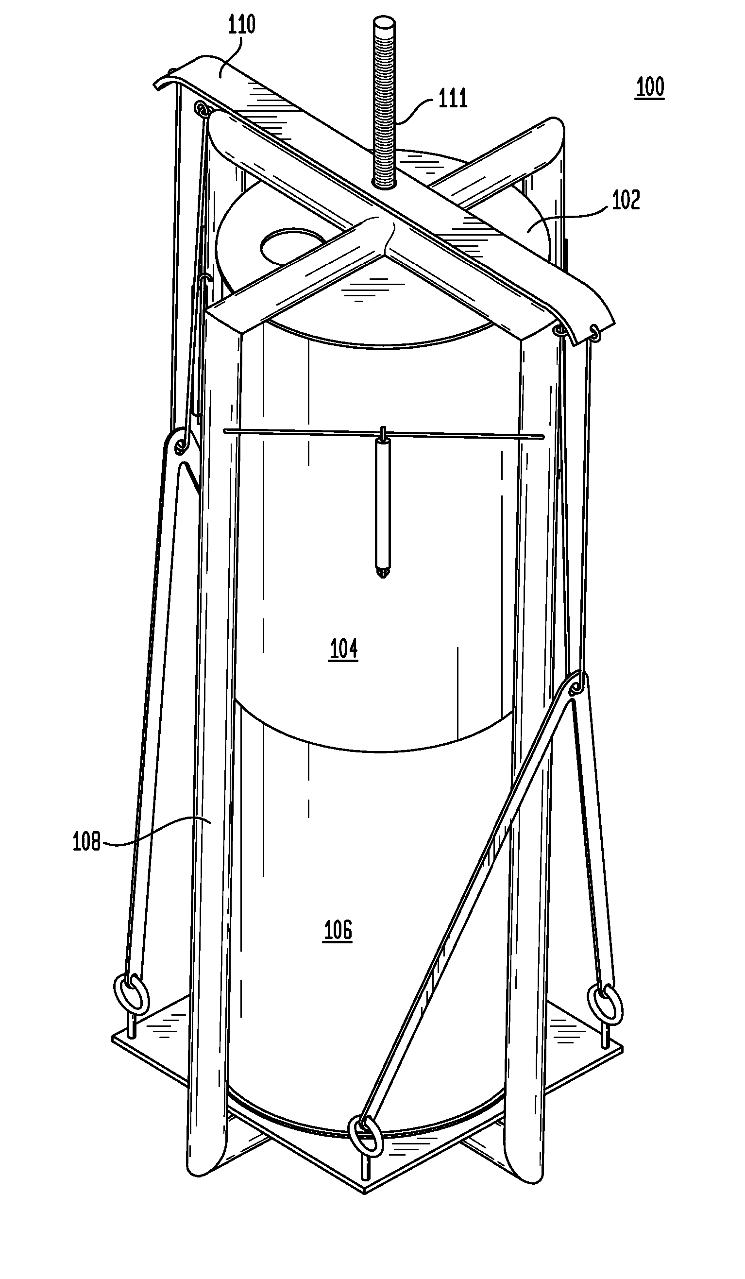
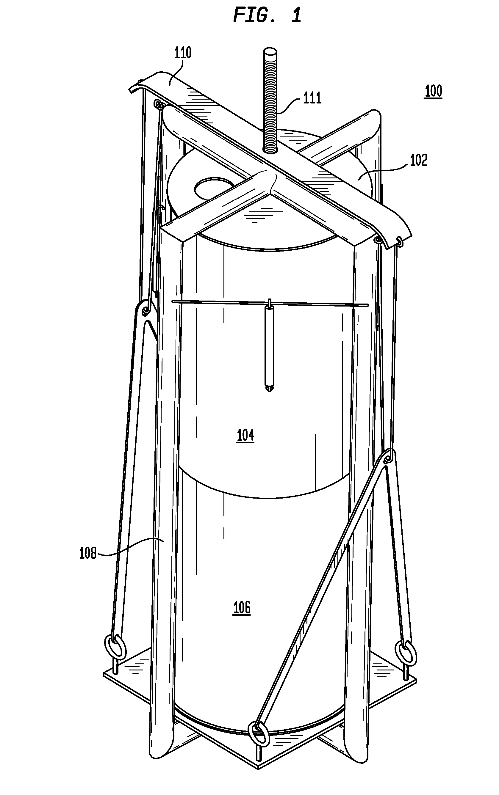
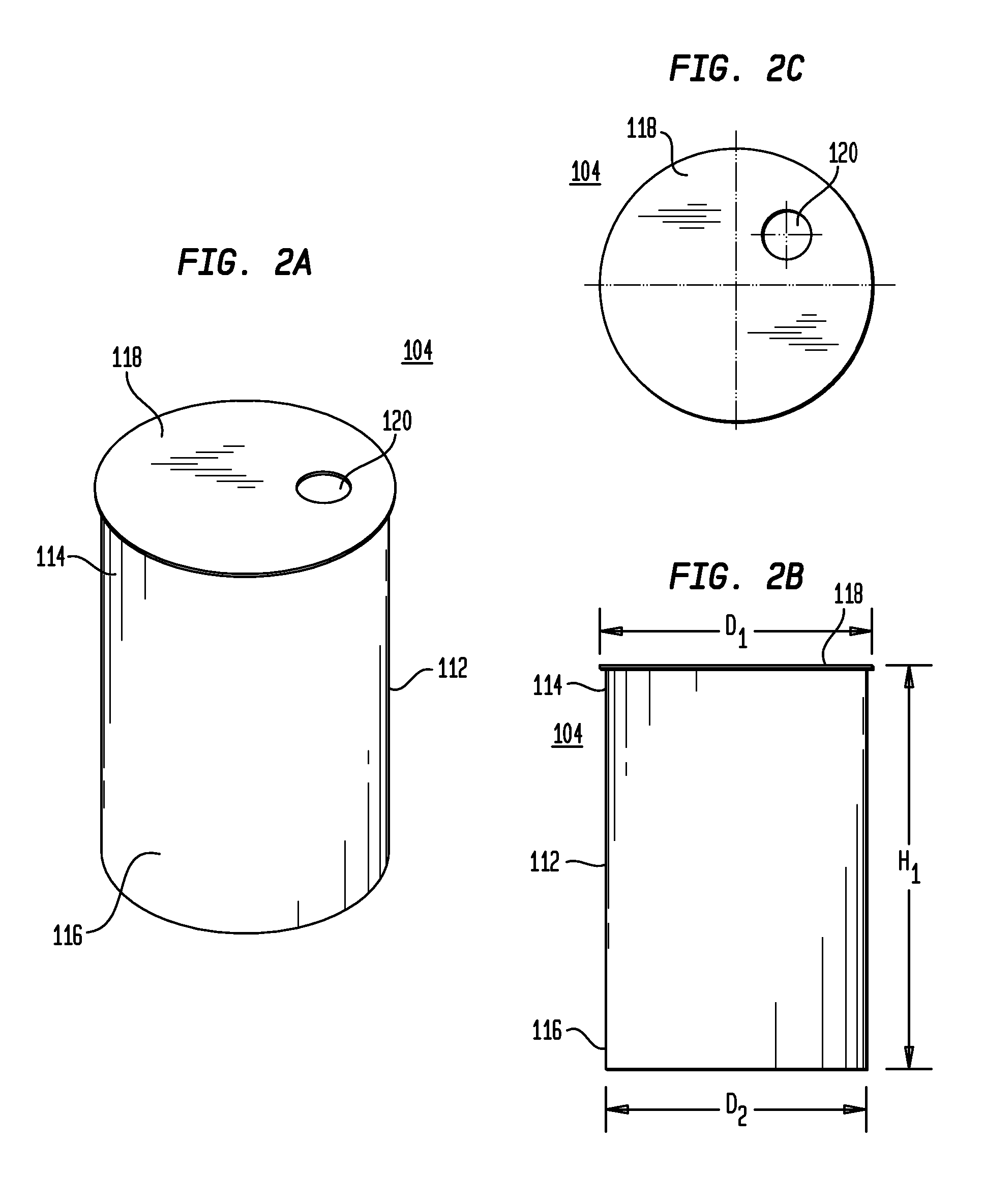
[0066] Referring to FIG. 1, in one preferred embodiment of the present invention, an energy system includes a vessel 100 having an expandable and collapsible chamber 102 having an upper chamber section 104 and a lower chamber section 106. The vessel 100 includes a support frame 108 that surrounds the chamber 102 and a mounting bracket 110 overlying an upper end of the support frame 108. The vessel includes a torque-generating line 111 ...


PUM


Abstract

A system for producing energy includes expandable vessels that are submerged in a liquid. The vessels are collapsible for sinking in the liquid due to gravitational forces and are expandable for rising in the liquid due to buoyancy forces. As the vessels sink in the liquid, the vessels rotate a shaft for generating energy. In one embodiment, the system includes a tank holding a liquid, an air-tight, expandable vessel disposed within the liquid and being adapted to move reciprocally between upper and lower ends of the tank, a conduit attached to the vessel for passing gas into and out of the vessel, and a linkage for selectively coupling the vessel with a rotatable shaft. The vessel is moveable between a collapsed state in which the vessel sinks in the liquid due to gravitational forces and an expanded state in which the vessel rises in the liquid due to buoyancy forces.

Description

CROSS-REFERENCE TO RELATED APPLICATIONS [0001] The present application claims the benefit of U.S. Provisional Application Ser. No. 60 / 848,337, filed Sep. 28, 2006, the disclosure of which is hereby incorporated by reference herein.BACKGROUND OF THE INVENTION [0002] 1. Field of the Invention [0003] Embodiments of the present invention generally relate to systems and methods for producing energy. More specifically, embodiments of the present invention relate to systems and methods that use gravity and buoyancy for producing energy. [0004] 2. Description of the Related Art [0005] There are many different systems and techniques used for producing energy. For example, power plants are typically located near rivers and dams. The power plants use the force of flowing water to rotate turbines, which, in turn, produce energy such as electricity. One problem with using water as an energy source, however is that the power plants must be located adjacent the supply of water. [0006] Another type...

Claims


Application Information

Patent Timeline
Patent Type & Authority Applications(United States)
IPC IPC(8): F03B17/04
CPCF03B17/025Y02E10/20F03B17/04
Inventor RAZACK, IZRAFEEL
Owner PASSIVE ENERGY
Why Eureka
Try Eureka