Bracing for Collapsible Boat

a technology for boats and ribs, applied in special-purpose vessels, vessel construction, transportation and packaging, etc., can solve the problems of not being able to include ribs in the same way, not being able to resist twisting in many collapsible boats, and being difficult to manipulate. , to achieve the effect of minimising damage to other boats

Inactive Publication Date: 2008-04-24
QUICKBOATS
View PDF18 Cites 8 Cited by
  • Summary
  • Abstract
  • Description
  • Claims
  • Application Information

AI Technical Summary

Benefits of technology

[0020] In a preferred embodiment of bracing at the bow of the boat, the anchoring position is located on a collapsible two-piece nose cone. The nose cone includes two resilient arms which, when in an assembled configuration, form a curved prow of the boat. This allows the assembled boat to be easily manipulated from the front, and also acts to minimise damage to other boats in the event of a low-speed collision. The resilient arms may have a gap between their outer ends in the assembled configuration to allow for the passing of a rope or chain between the arms.

Problems solved by technology

The stress exerted on the boat hull by the outboard motor mounted on the stern members, however, has meant that it has not generally been possible to use outboard motors whose power exceeds about 4 horsepower.
In a collapsible boat, it has not proved possible to include ribs in the same way, although attempts have been made.
As a result, many collapsible boats have a limited capacity to resist twisting as a result of torsional forces.
Such bracing is largely ineffectual, as the seat is spaced from the boat hull, and has no direct connection to panels at the base of the boat or to the transom.
A suitable coupling arrangement can be complex, and make assembly of the boat more difficult.

Method used


Image

  • Bracing for Collapsible Boat
  • Bracing for Collapsible Boat
  • Bracing for Collapsible Boat

Examples


Embodiment Construction

)

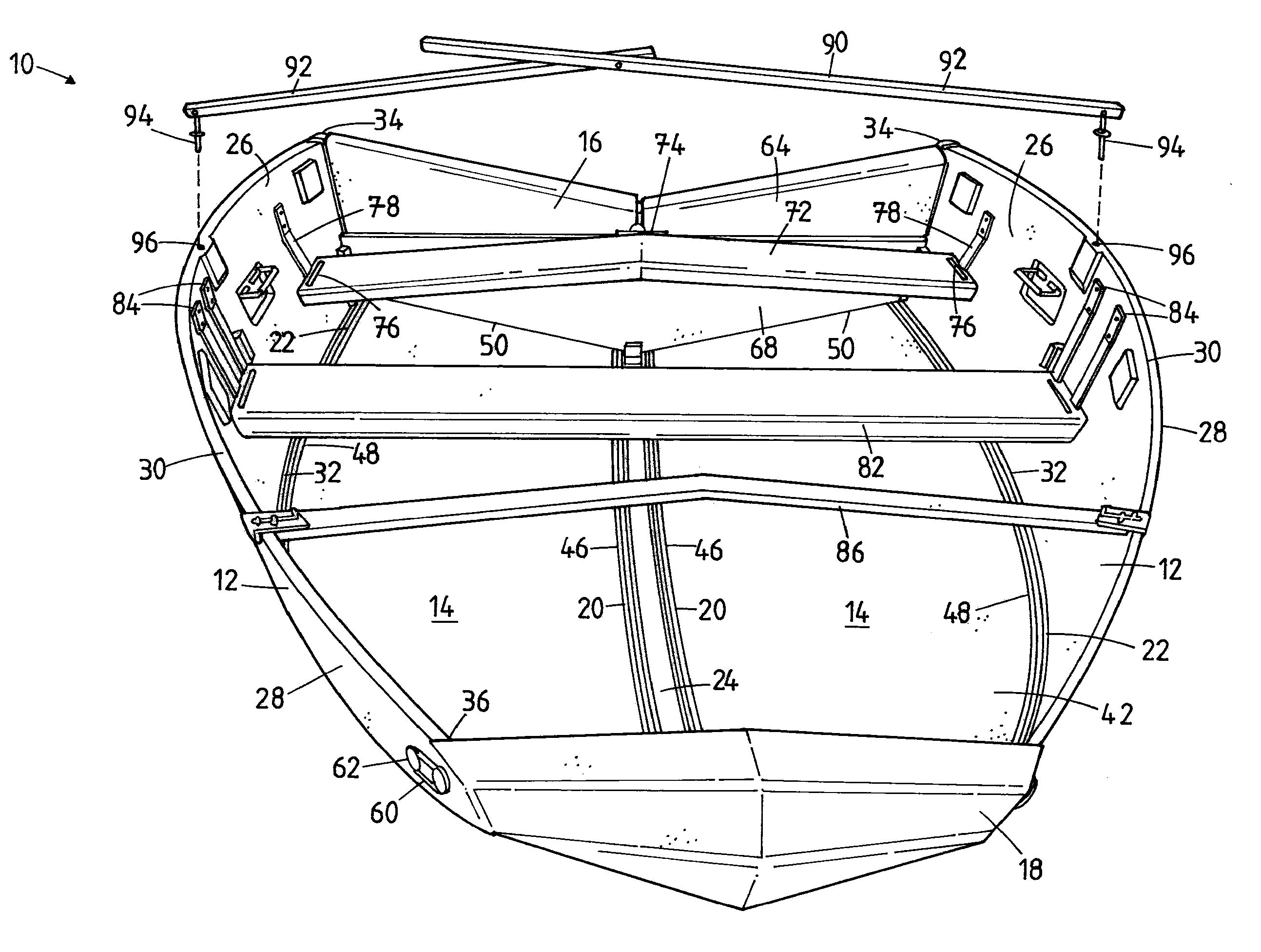
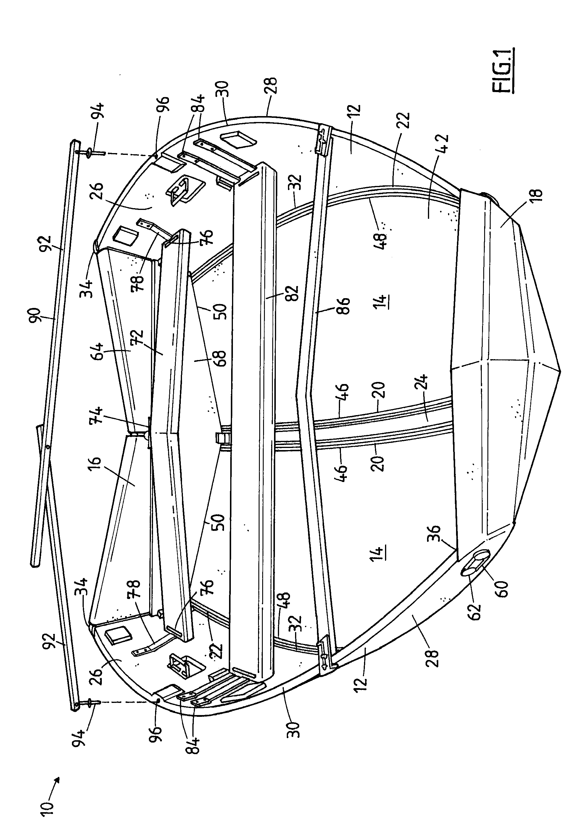
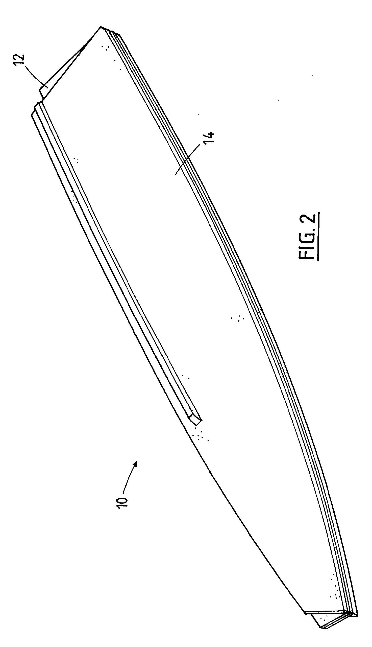
[0041] Referring to FIGS. 1 to 7, there is shown a collapsible boat hull 10 comprising a pair of side panels 12, a pair of bottom panels 14, a stern member 16, and a bow member 18. Each bottom panel 14 has a first continuous hinge 20 along an inner edge thereof, and a second continuous hinge 22 along an outer edge thereof. In the embodiment of the drawings, each of the first continuous hinges 20 is connected to respective first and second sides of a centrally disposed keel member 24. In an alternative keel-less embodiment of the invention, the two bottom panels 14 are connected along a single common first continuous hinge 20.

[0042] Each bottom panel 14 is connected to a corresponding side panel 12 along its second continuous hinge member 22. Spines of each of the first and second continuous hinge members 20,22 have resilient flexibility along respective longitudinal and transverse planes thereof, thereby facilitating the bottom and side panels 14, 12 to be collapsed and folded fro...


PUM


Abstract

A collapsible boat hull comprises a pair of bottom panels and a pair of side panels, connected by continuous hinges. Erection of the boat causes a fore portion of the bottom panels to curve upwards, and fore portions of the side panels to curve inwards. The boat also includes a V-shaped rear seat, which acts to transfer force and vibration from a rearwardly mounted outboard motor to the side walls of the boat. The boat is braced between its seats and the hull.

Description

BACKGROUND OF THE INVENTION [0001] The present invention relates to collapsible boats, such as those formed by panels hinged together. More particularly, the invention relates to a method for bracing such boats when in an erected configuration to provide stiffness and rigidity. [0002] It is known to provide collapsible boat hulls, comprising a pair of hingedly interconnected bottom panels and a pair of side panels hinged to the bottom panels. Such boats can be collapsed and folded along the hinging edges of the panels into a substantially flat configuration for ease of transport and storage, and then erected into a suitable hull shape for use on water. Typically, collapsible boat hulls are also provided with a stern member functioning as a transom, a bow member, and seats which are mounted onto the boat hull when the boat hull is in an erected configuration. It is important that the junction between the boat hull and the bow member, and the boat hull and the stern member, are leak-p...

Claims


Application Information

Patent Timeline
Patent Type & Authority Applications(United States)
IPC IPC(8): B63B7/02
CPCB63B7/02
Inventor AGER, GAVIN R.PIVIALI, STEFANOKHOURY, EDWARD J.
Owner QUICKBOATS
Why Eureka
Try Eureka