
Engine Start Control Apparatus, Engine Start Control Method, and Motor Vehicle Equipped with Engine Start Control Apparatus

a technology of engine start and control apparatus, which is applied in the direction of electric control, ignition automatic control, instruments, etc., can solve the problems of poor emission of unconsumed fuel gas, poor start of engine cranking, poor combustion of air-fuel mixture in the cylinder, etc., to stabilize the level of combustion torque, and improve the startability of the engin

Active Publication Date: 2008-04-24
TOYOTA JIDOSHA KK +1
View PDF11 Cites 39 Cited by
  • Summary
  • Abstract
  • Description
  • Claims
  • Application Information

AI Technical Summary

Benefits of technology

[0004] The object of the invention is thus to eliminate the drawbacks of the prior art technique and to reduce a misfire rate on a start of an engine and thereby improve the startability of the engine. The object of the invention is also to prevent poor emission on the start of the engine. The object of the invention is further to stabilize a level of torque generated on the start of the engine and thereby improve the drivability on the start of the engine.
[0033] The present invention is still further directed to a vehicle with any of the engine start control apparatuses of the invention descried above. Thus, the vehicle of the invention realizes improved startability of the engine, prevents poor emission, or realizes stabilized level of combustion torque generated on the start of the engine and improved drivability on the start of the engine.

Problems solved by technology

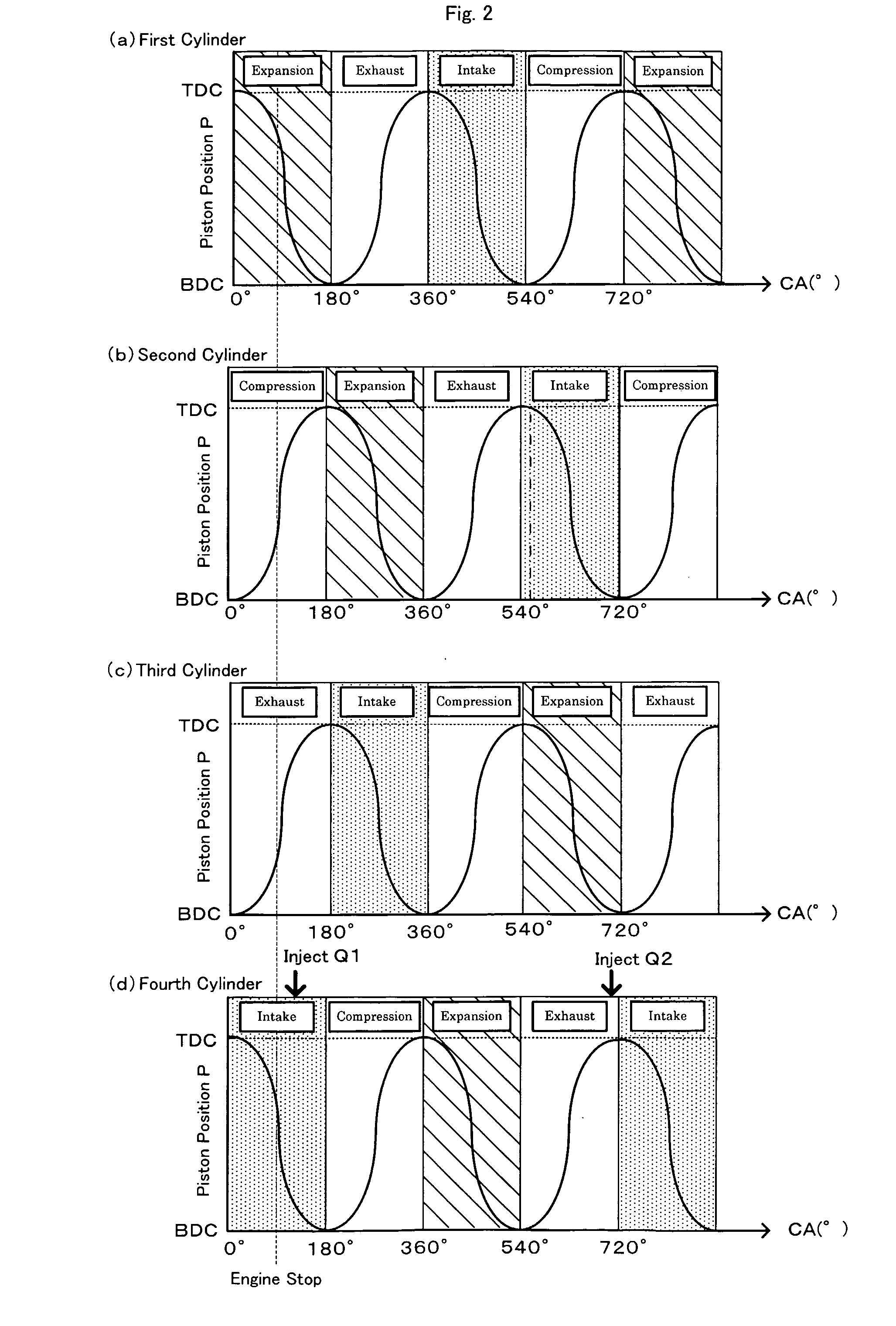
In the prior art engine start control apparatus, however, some piston stop position of the cylinder stopping in the intake stroke in the engine stop state may cause insufficient introduction of the air-fuel mixture into the cylinder in a first intake stroke and may thus result in a misfire at the start of engine cranking.
The misfire undesirably lengthens the starting time of the engine and causes poor emission by the unconsumed fuel gas.
Under some piston stop position of the cylinder stopping in the intake stroke in the engine stop state, the insufficient introduction of the fuel into the cylinder in the first intake stroke tends to produce the air-fuel mixture unsuitable for combustion in the cylinder.
The combustion torque generated from the air-fuel mixture unsuitable for combustion is significantly smaller than the combustion torque generated from the air-fuel mixture suitable for combustion.
This undesirably makes the level of torque changeable and unstable on the start of the engine.

Method used


Image

  • Engine Start Control Apparatus, Engine Start Control Method, and Motor Vehicle Equipped with Engine Start Control Apparatus
  • Engine Start Control Apparatus, Engine Start Control Method, and Motor Vehicle Equipped with Engine Start Control Apparatus
  • Engine Start Control Apparatus, Engine Start Control Method, and Motor Vehicle Equipped with Engine Start Control Apparatus

Examples


first embodiment

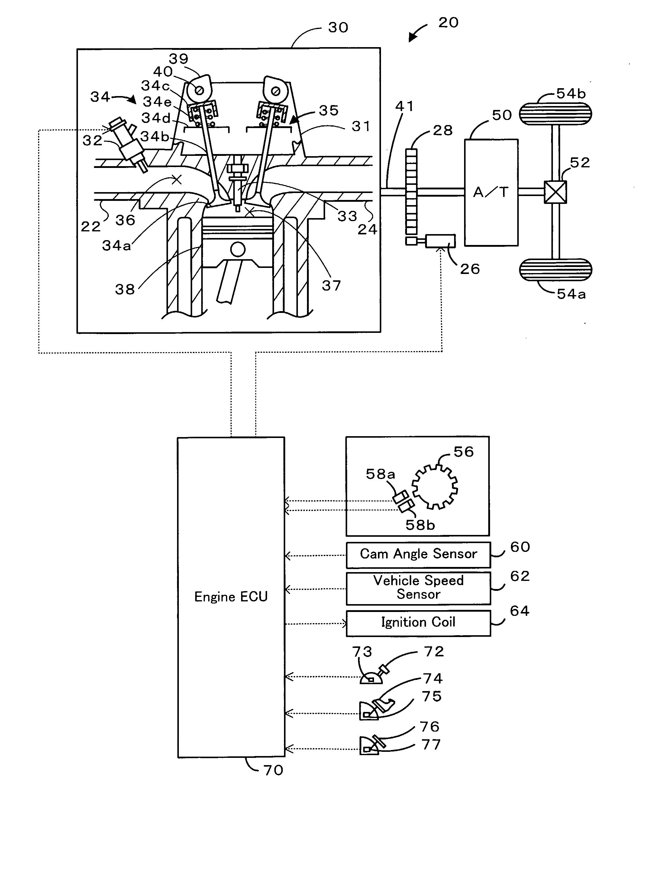
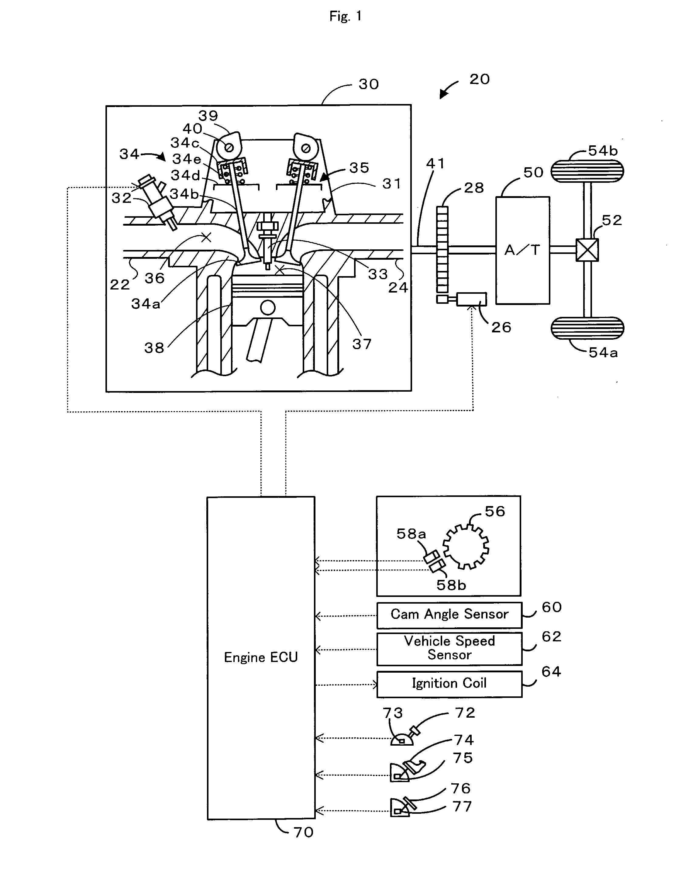
[0047] A first embodiment of the invention is described below with reference to the accompanied drawings. FIG. 1 schematically illustrates the configuration of a motor vehicle 20 having idle stop function in the first embodiment of the invention. The motor vehicle 20 of the first embodiment with the idle stop function includes an engine 30 that is driven with a fuel, for example, gasoline, a starter motor 26 that starts the engine 30, and an engine electronic control unit 70 (hereafter referred to as engine ECU) that controls the operations of the respective constituents of the engine 30. In the engine 30, an injector 32 injects the fuel (gasoline) into an intake port 36 of each of multiple cylinders 31, and an ignition plug 33 ignites a mixture of the intake air and the injected fuel (air-fuel mixture) in each cylinder 31.

[0048] The engine 30 is a 4-cylinder engine in this embodiment. Each of the four cylinders 31 is designed to have a port structure, where gasoline is injected by...

second embodiment

[0074] A second embodiment of the invention regards the motor vehicle 20 with the idle stop function, which has the same configurations as those of the first embodiment. The like elements to those of the first embodiment are thus expressed by the like numerals and symbols. The primary difference from the first embodiment is automatic engine restart control. The motor vehicle 20 of the second embodiment with the idle stop function executes the automatic engine stop control of FIG. 3 in the same manner as the first embodiment. The ignition plug 33 of this embodiment corresponds to the ignition unit of the invention, and the engine ECU 70 is equivalent to the ignition control module of the invention.

[0075]FIG. 7 is a flowchart showing an automatic engine restart control routine of the second embodiment. This control routine is executed by the engine ECU 70 at preset time intervals (for example, at every several msec) after an automatic stop of the engine 30 by the automatic engine sto...


PUM


Abstract

In a motor vehicle with idle stop function, upon satisfaction of preset engine restart conditions (step S205), automatic engine restart control refers to a preset map representing a variation in amount of fuel Q1, which is to be initially injected into a cylinder Cyin stopping in an intake stroke, against the piston stop position Pin of the cylinder Cyin, and specifies the amount of fuel Q1 corresponding to the detected piston stop position Pin of the cylinder Cyin (step S220). The automatic engine restart control then controls an injector to inject the specified amount of fuel Q1 into an intake port of the cylinder Cyin (step S230). Under the condition that the piston stop position Pin of the cylinder Cyin suggests low gas intake performance, the increased amount of fuel Q1 is injected into the intake port of the cylinder Cyin. This arrangement desirably reduces a misfire rate at the timing of first combustion and thereby improves the startability of an engine. When the amount of fuel Q1 specified at step S220 is equal to zero, the cylinder Cyin is not subject to the first combustion. Such control desirably prevents poor emission.

Description

FIELD OF THE INVENTION [0001] The present invention relates to an engine start control apparatus, a corresponding method, and vehicle with the apparatus mounted thereon. BACKGROUND ART [0002] Engine start control apparatuses have been proposed to inject a first supply of fuel for restarting an engine into a cylinder stopping in an intake stroke in an engine stop state, to start engine cranking, and to subsequently ignite the air-fuel mixture for first combustion in the cylinder stopping in the intake stroke. For example, an engine start control apparatus disclosed in Japanese Patent Laid-Open Gazette No. 2003-56383 injects the first supply of fuel for restarting the engine into the cylinder during a stop of the engine and thereby shortens the starting time of the engine. DISCLOSURE OF THE INVENTION [0003] In the prior art engine start control apparatus, however, some piston stop position of the cylinder stopping in the intake stroke in the engine stop state may cause insufficient in...

Claims


Application Information

Patent Timeline
Patent Type & Authority Applications(United States)
IPC IPC(8): F02D41/06F02N17/00F02D17/00F02D29/02F02D45/00F02N15/00F02N99/00F02P5/15
CPCF02D41/009F02D41/062F02D41/065F02N19/005F02D2041/0095F02D2200/1015F02N11/0814F02D2041/0092
Inventor TAKAHASHI, SHIGENORI
Owner TOYOTA JIDOSHA KK
Learn More