

Disposable Sleep And Breathing Monitor
a monitor and sleep technology, applied in the field of air flow monitors, can solve the problems of not being able to quantify the quantitative measurement of ventilation has not been well established in clinical diagnostics, and the use of pneumotachographs is widely used, so as to improve the degree of upper airway function. the effect of adverse effects
- Summary
- Abstract
- Description
- Claims
- Application Information
AI Technical Summary
Benefits of technology
Problems solved by technology
Method used
Image

Examples
Embodiment Construction
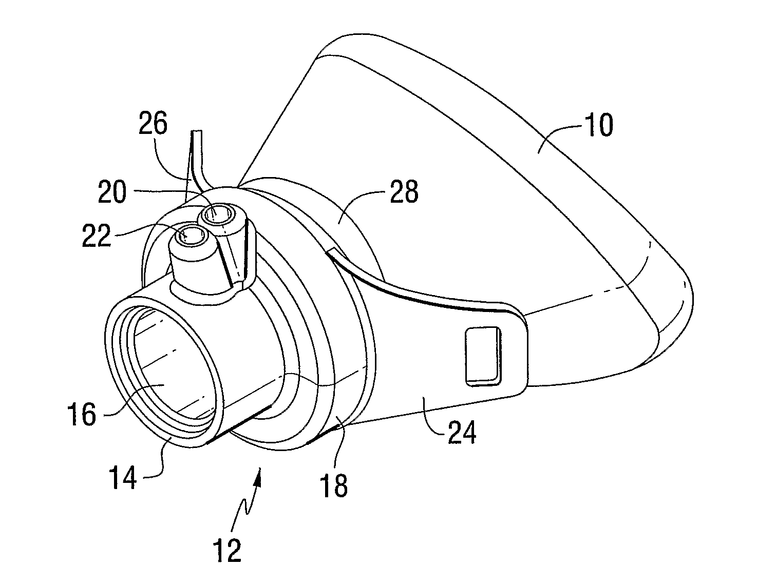
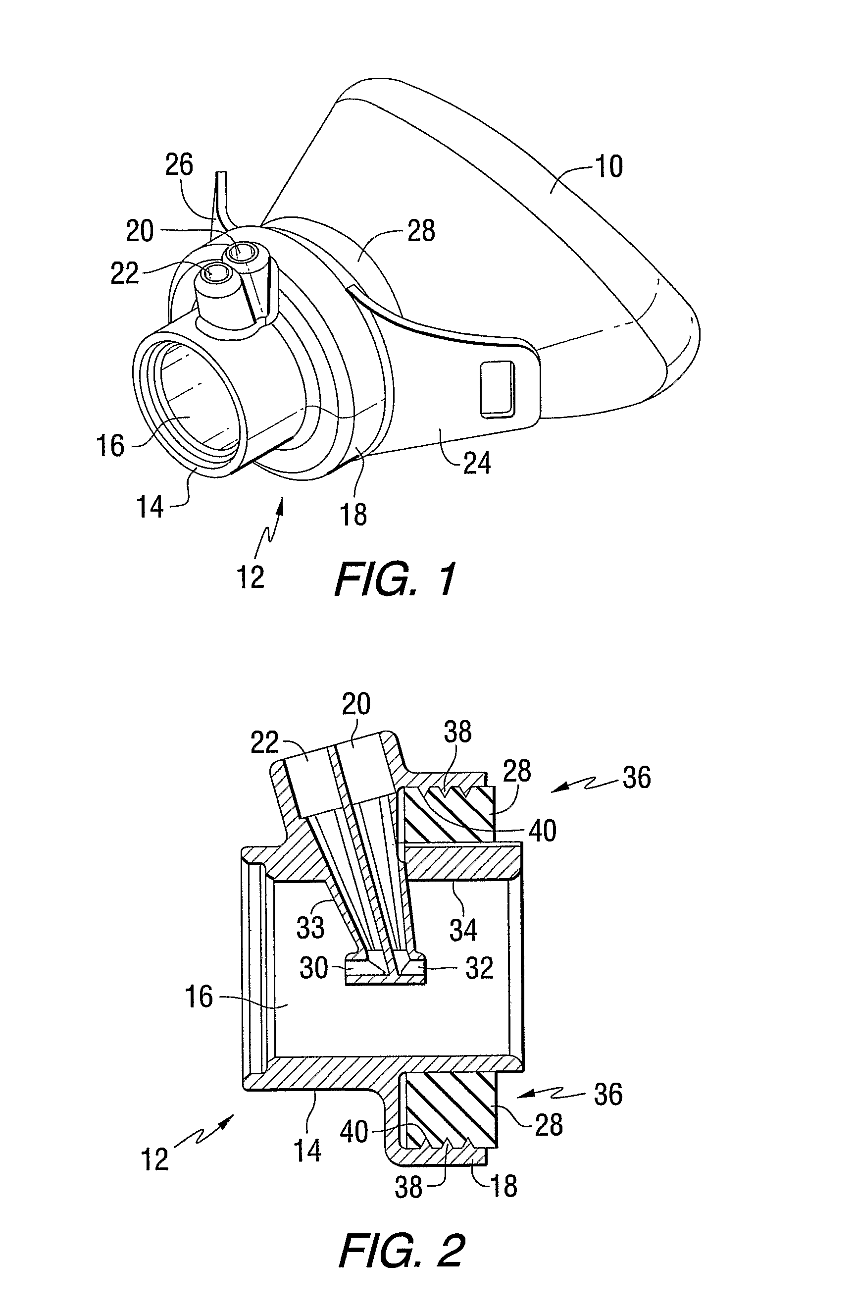
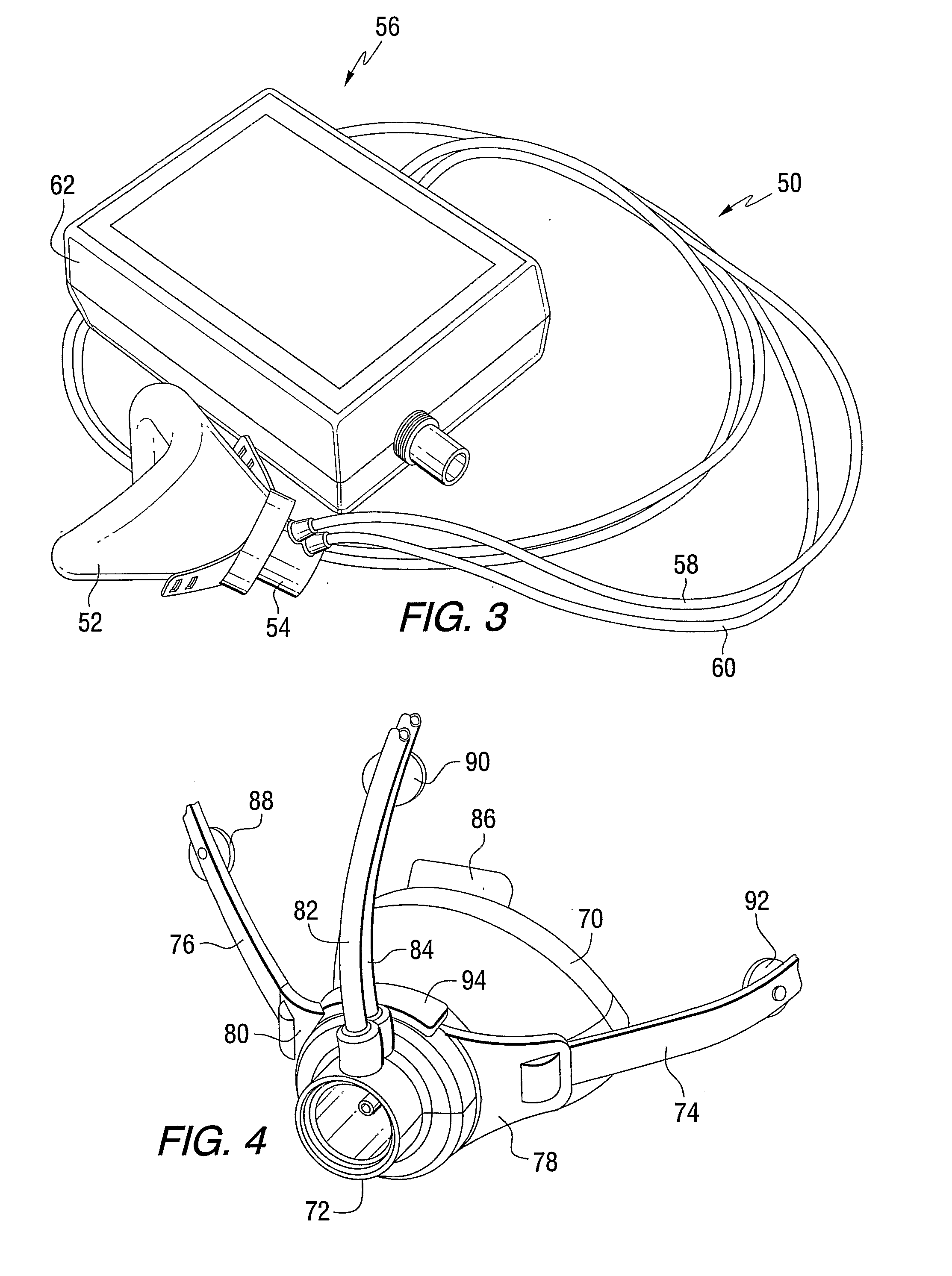
[0026] This invention provides a light weight, low dead-space, disposable breathing sensor and a monitor which can be used for long term measurements of tidal breathing through a nose mask, face mask, tracheostomy or ventilator tubing without adding significant dead space to the airway. In one application, the invention is used for adults and demonstrates that the combined dead space of a small nasal mask and the flow sensor is less than 15 milliliter. Thus, the invention provides an apparatus for measuring air flow quantitatively for prolonged time in non-intubated (Model A in Table 2, and FIGS. 1-4 below) or intubated (Model B in Table 2, and FIG. 5 below) individuals while keeping the added dead space in a range known to be insignificant during sleep. Data from sleep studies in adults show that the breathing monitor is extraordinarily comfortable when worn during sleep and provides an accurate, quantitative measurement of ventilation and respiratory dynamics during sleep.
[0027] ...
PUM
 Abstract
Description
Claims
Application Information