Frameless glass door clamp

a frameless glass and door technology, applied in the direction of washstands, scaffold accessories, lighting support devices, etc., can solve the problems of large stamping force, impracticality, and inability to meet the needs of welding adjacent edges, and achieve the effect of easy manufacturing

Inactive Publication Date: 2008-04-24
DOOR & WINDOW HARDWARE
View PDF6 Cites 19 Cited by
  • Summary
  • Abstract
  • Description
  • Claims
  • Application Information

AI Technical Summary

Benefits of technology

[0015]The primary objective of the present invention is to provide a framel

Problems solved by technology

Forming the right-angled edges of the base cover (90) and the cap cover (70) requires a large stamping force and may be impractical or require additional fabrication proc

Method used


Image

  • Frameless glass door clamp
  • Frameless glass door clamp
  • Frameless glass door clamp

Examples


Embodiment Construction

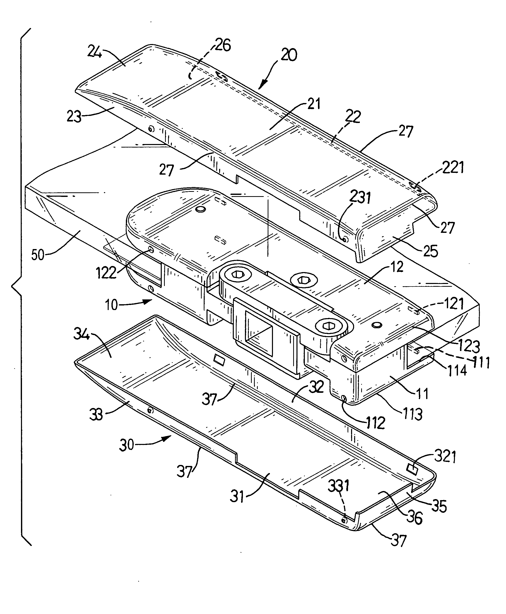
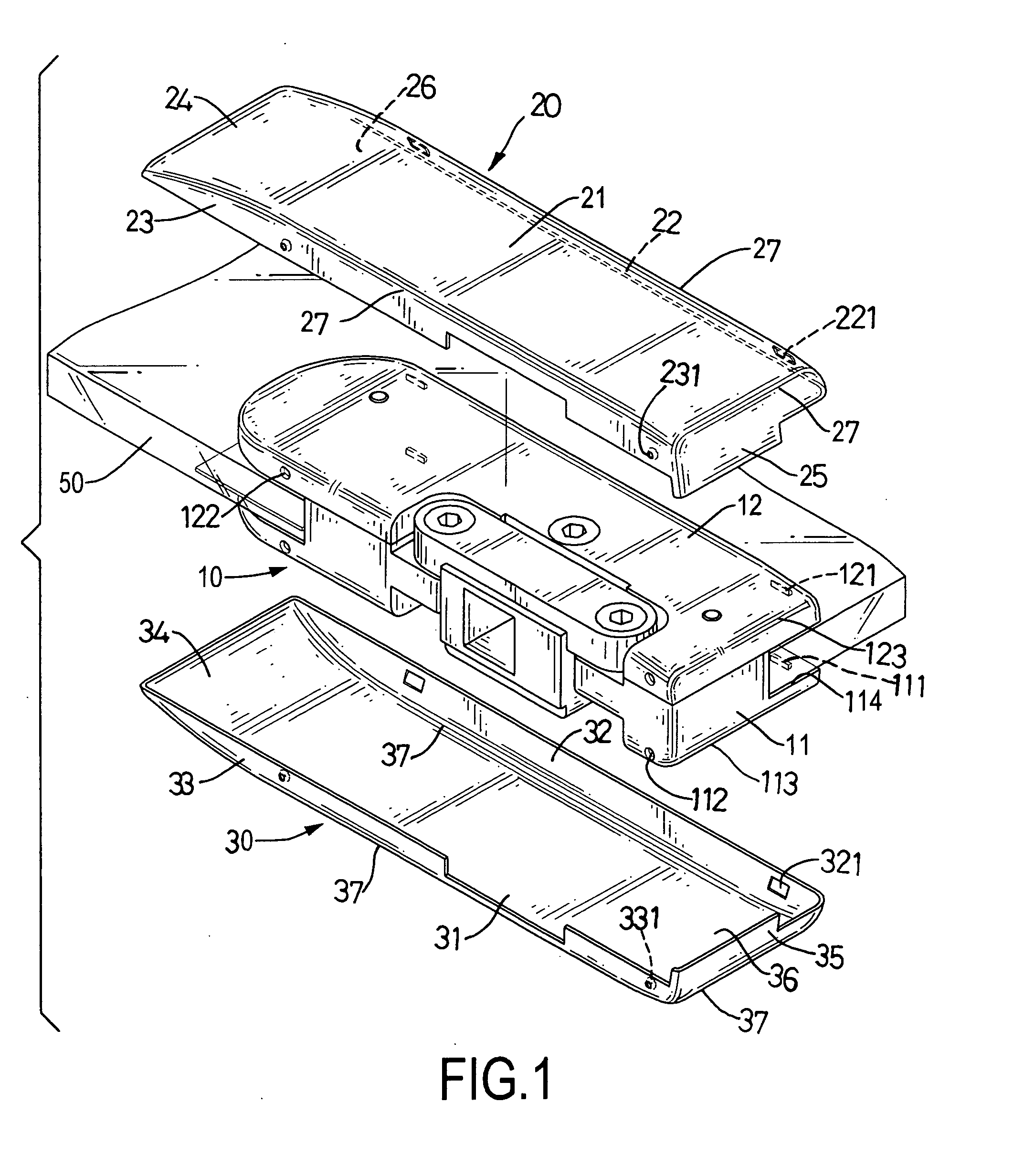
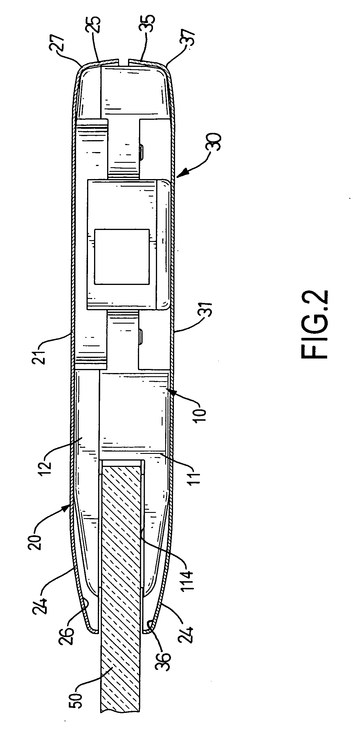
[0030]With reference to FIGS. 1, 6, 7 and 8, a frameless glass door clamp in accordance with the present invention is mounted on a frameless glass door (50) or a glass doorframe (51), may be rectangular or L-shaped and comprises a clamping member (10), a base cover (30, 30A, 30B, 30C) and a cap cover (20, 20A, 20B, 20C).

[0031]With further reference to FIGS. 2, 3, 4 and 5, the clamping member (10) clamps onto a frameless glass door (50) or a glass doorframe (51) and comprises a base (11) and a cap (12).

[0032]The base (11) has a base side surface, an inner face and a clamping recess (114). The base side surface has an inner longitudinal edge, an outer longitudinal edge, an inner transverse edge, an outer transverse edge, at least one optional boss (111), at least one optional detent (112), and multiple outer edges (113). The at least one boss (111) is formed on and protrudes from the inner longitudinal edge of the base (11). The detent (112) is defined in the outer longitudinal edge o...


PUM


Abstract

A frameless glass door clamp has a clamping member, a base cover and a cap cover. The clamp member has a base side surface and a cap side surface. The base cover is mounted on the base side surface and has a panel, multiple flanges, a tapered face and multiple rounded outer edges. The cap cover is mounted on the cap side surface and has a panel, a multiple flanges, a tapered face and multiple rounded outer edges. Because the outer edges of the base and cap covers are rounded, the frameless glass door clamp is much less likely to injure people or damage objects and is easier to manufacture.

Description

BACKGROUND OF THE INVENTION[0001]1. Field of Invention[0002]The present invention relates to a frameless glass door clamp, and more particularly to a frameless glass door clamp that is safe for people and can be manufactured easily.[0003]2. Description of the Related Art[0004]With reference to FIG. 9, a conventional frameless glass door clamp in accordance with the prior art is mounted on an edge or at a corner of a frameless glass door (50) so the frameless glass door (50) can be connected pivotally to a doorframe, a handle can be attached to the frameless glass door (50), or a lock can be mounted on the frameless glass door (50).[0005]The conventional frameless glass door clamp comprises a clamping member (80), a base cover (90) and a cap cover (70).[0006]The clamping member (80) is mounted on an edge of the frameless glass door (50) and comprises a base (81) and a cap (82).[0007]The base (81) has an inner face, an inner longitudinal edge, an outer longitudinal edge, an inner tran...

Claims


Application Information

Patent Timeline
IPC IPC(8): F21V21/00
CPCE05D5/0246E05D11/0054E05D2005/0261E05Y2201/11E05Y2800/16E05Y2800/672Y10T16/533E05F3/10E05Y2900/132E05F3/227E05D7/081Y10T16/534E06B3/02
Inventor CHANG, WEI-HUNGHSIEH, CHIH-LUN
Owner DOOR & WINDOW HARDWARE
Why Eureka
Try Eureka