Spark plug designed to ensure stability of ignition of air-fuel mixture

a technology of spark plugs and air-fuel mixtures, which is applied in the direction of spark plugs, sparking plugs, basic electric elements, etc., can solve the problems of failure to completely burn the air-fuel mixture, and achieve the effect of enhancing the shaping of the flow

Inactive Publication Date: 2008-04-24
DENSO CORP +1
View PDF28 Cites 18 Cited by
  • Summary
  • Abstract
  • Description
  • Claims
  • Application Information

AI Technical Summary

Benefits of technology

[0018] The slant peripheral surface works as a stream shaper to shape a vortex stream of the air-fuel mixture flowing toward the top of the porcelain insulator into a stream of the air-fuel mixture along the slant peripheral surface which flows away from the top of the porcelain insulator (i.e., deep inside a combustion chamber of the engine). This minimizes the possibility that the flame, as produced near the spark gap, will be carried by the stream of the air-fuel mixture in

Problems solved by technology

This results in a failure in burni

Method used


Image

  • Spark plug designed to ensure stability of ignition of air-fuel mixture
  • Spark plug designed to ensure stability of ignition of air-fuel mixture
  • Spark plug designed to ensure stability of ignition of air-fuel mixture

Examples


third embodiment

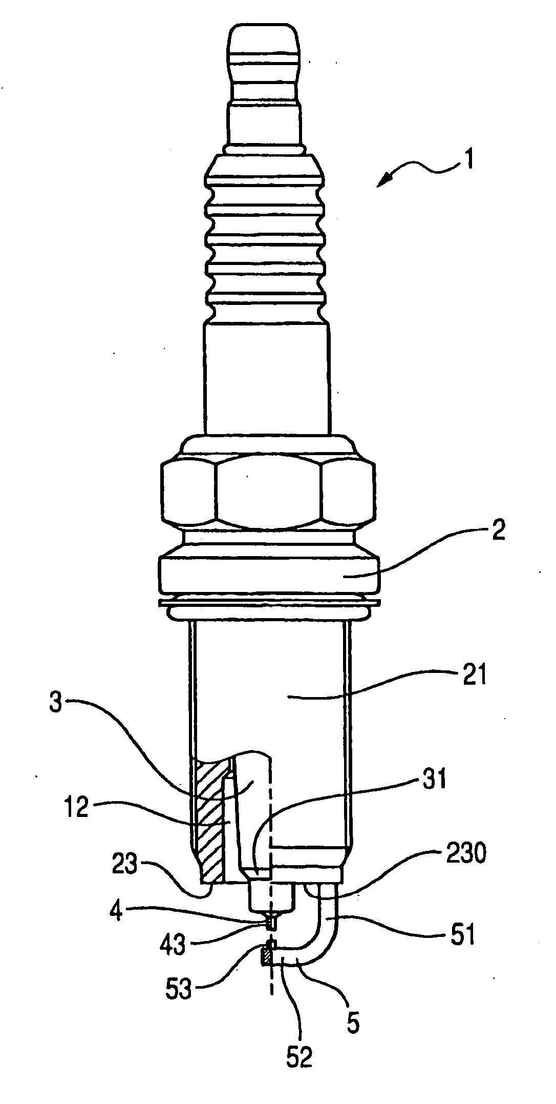
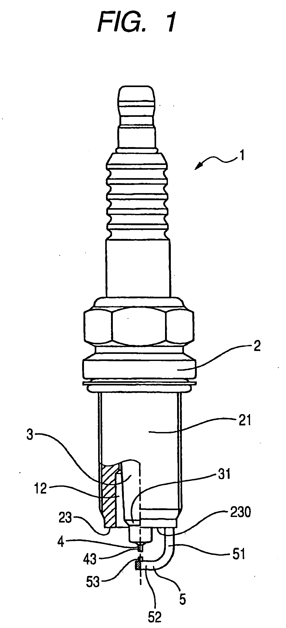
[0064]FIGS. 7 and 8 illustrate the spark plug 1 according to the invention.

first embodiment

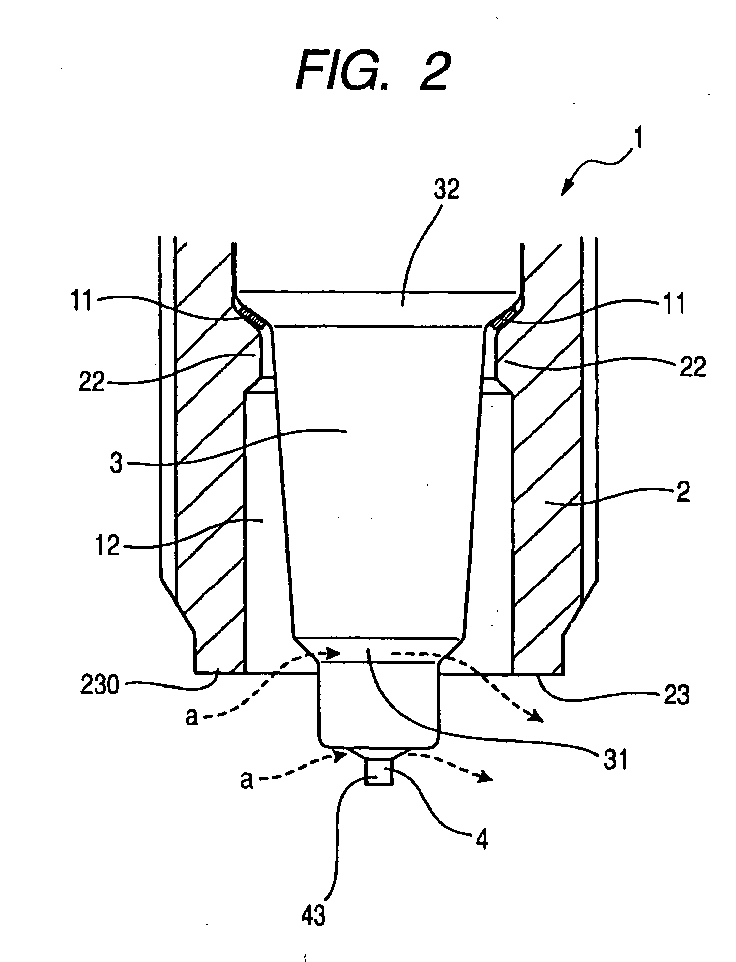
[0065] The porcelain insulator 3 has an annular slant surface 34 formed on an inner peripheral wall thereof. The slant surface 34 faces inwardly of the porcelain insulator 3. The porcelain insulator 3 does not have the tapered surface 31, as illustrated in FIG. 2. Other arrangements are identical with those in the first embodiment, and explanation thereof in detail will be omitted here.

[0066] The slant surface 34 works as a stream shaper to shape the vortex stream of the air-fuel mixture flowing to the top of the porcelain insulator 3 into a stream of the air-fuel mixture, as indicated by the broken arrow a, along the slant surface 34 around the tapered surface 31. Specifically, the vortex stream of the air-fuel mixture flowing to the top of the porcelain insulator 3 is oriented as the stream, as indicated by the arrow a, away from the top of the porcelain insulator 3 (i.e., deep inside the combustion chamber). This minimizes the possibility that the flame, as produced near the spar...

fourth embodiment

[0067]FIGS. 9 and 10 illustrate the spark plug 1 according to the invention.

[0068] The porcelain insulator 3 has formed in a peripheral portion thereof an annular recess or groove 35 which is located near the top end surface 23 of the metal shell 2, i.e., closer to the top end of the porcelain insulator 3 than the inner bulged portion 22 of the metal shell 2. The annular groove 35 is of an arc-shape in cross section and extends over the whole of circumference of the porcelain insulator 3.

[0069] The metal shell 2 has formed in an inner wall thereof closer to the top end surface 23 an annular recess or groove 25 facing the annular groove 35 of the porcelain insulator 3 to define an annular air chamber therebetween which is wider in a direction perpendicular to the length of the spark plug 1 (i.e., the metal shell 2) than a portion of the pocket 12 closer to the inner bulged portion 22.

[0070] The annular groove 35 of the porcelain insulator 3 works a stream shaper to shape a flow of ...


PUM


Abstract

A spark plug for an internal combustion engine is provided which includes a hollow cylindrical metal shell with an open end portion to be exposed to a combustion chamber of the engine, a ground electrode joined to the metal shell, a center electrode disposed in the metal housing to define a spark gap between itself and the ground electrode. The spark plug also includes a stream shaper or a stream reflector geometrically formed on the metal shell and/or the porcelain insulator to shape a vortex steam of air-fuel mixture into a stream thereof which is oriented outside the spark plug or serves to decrease the amount of the air-fuel mixture into a pocket between the metal shell and the porcelain insulator. This ensures the stability of ignition of the air-fuel mixture.

Description

CROSS REFERENCE TO RELATED DOCUMENT [0001] The present application claims the benefit of Japanese Patent Application No. 2006-288239 filed on Oct. 24, 2006, the disclosure of which is incorporated herein by reference. BACKGROUND OF THE INVENTION [0002] 1. Technical Field of the Invention [0003] The present invention relates generally to a spark plug for internal combustion engines which may be employed in automotive vehicles, cogeneration systems, or gas feed pumps, and more particularly to an improved structure of such a spark plug designed to shape or orient a vortex stream of air-fuel mixture, thereby ensuring the stability of ignition of air-fuel mixture in a combustion chamber of the engine. [0004] 2. Background Art [0005] Japanese Patent First Publication No. 11-3765 (U.S. Pat. No. 6,846,214 B1) discloses a typical spark plug for internal combustion engines which includes a metal shell with an external mounting thread, a porcelain insulator retained in the metal shell, a cente...

Claims


Application Information

Patent Timeline
IPC IPC(8): H01T13/20
CPCH01T13/32H01T13/18
Inventor TAKADA, KENICHIROHANASHI, KENTAKEUCHI, TAKAYUKI
Owner DENSO CORP
Why Eureka
Try Eureka