
Vehicle occupant detection apparatus

a detection apparatus and vehicle technology, applied in the direction of identification means, pedestrian/occupant safety arrangements, instruments, etc., can solve the problems of degrading the reliability of the operation performance of the apparatus itsel

Inactive Publication Date: 2008-04-24
HONDA MOTOR CO LTD
View PDF11 Cites 29 Cited by
  • Summary
  • Abstract
  • Description
  • Claims
  • Application Information

AI Technical Summary

Benefits of technology

[0005]In view of the foregoing prior art problems, it is an object of the present invention to provide an improved vehicle occupant detection apparatus which can distinguish between normal and abnormal imaging operation of an image pickup device and thereby forestall a functional failure of the apparatus.
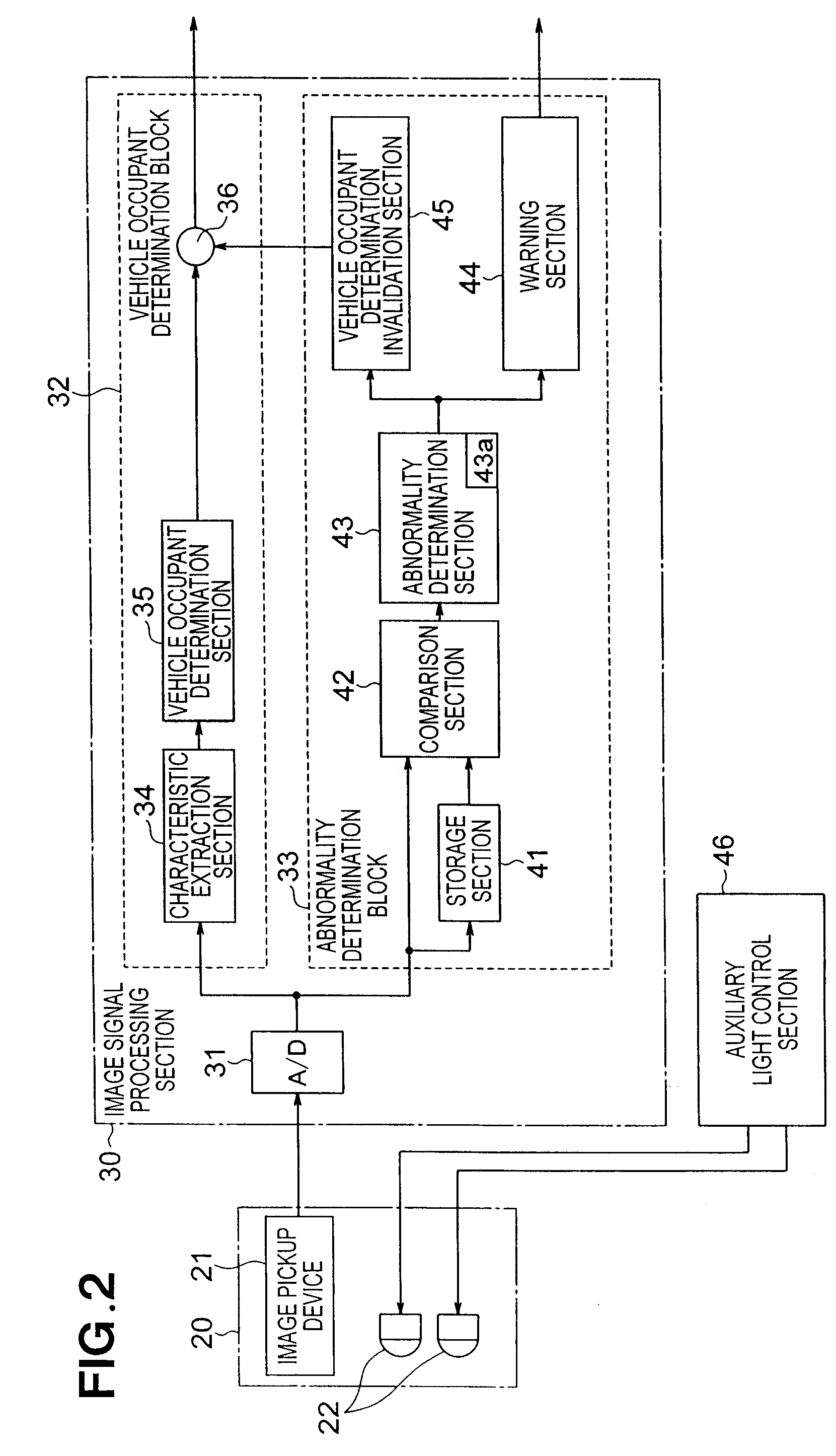
[0007]In imaging the vehicle occupant (i.e., object to be imaged), the vehicle occupant detection apparatus of the present invention images the vehicle occupant twice with the light emitting state of the light emitting element varied, so that it is possible to determine, on the basis of a difference between the imaging information acquired through the two imaging operations, normality or abnormality of the imaging information. With this arrangement, the present invention can forestall any functional failure of the vehicle occupant detection apparatus.
[0008]Preferably, the vehicle occupant detection apparatus comprises a plurality of the light emitting elements, and the comparison section compares the imaging information provided by the image pickup device with the light emitting element set (i.e., operating) in a partial illuminating state and the imaging information provided by the image pickup device with the light emitting element set (i.e., operating) in a full illuminating state. In this case, the vehicle occupant is imaged twice with the auxiliary light emitting state of the light emitting element varied between the partial illuminating state and the full illuminating state, so that the difference between the imaging information acquired through the two imaging operations can be extracted accurately.
[0009]Preferably, the comparison section compares the imaging information provided by the image pickup device with at least one light emitting element set in a low-light-amount illuminating state and the imaging information provided by the image pickup device with at least one light emitting element set in an illuminating state with a predetermined light amount greater than the low light amount. In this case, the vehicle occupant is imaged twice with the auxiliary light emitting state of the light emitting element varied between the low-light-amount illuminating state and the illuminating state using the predetermined light amount greater than the low light amount, so that the difference between the imaging information acquired through the two imaging operations can be extracted accurately.
[0011]Preferably, the vehicle occupant detection apparatus further comprises an abnormality notifying section for notifying abnormality of the imaging information on the basis of a determination signal output by the abnormality determination section. With such an arrangement, the present invention can forestall any functional failure of the vehicle occupant detection apparatus.
[0013]As set forth above, the vehicle occupant detection apparatus of the present invention images the vehicle occupant twice with the light emitting state of the light emitting element varied, and normality or abnormality of the imaging information is determined on the basis of a difference between the imaging information acquired through the two imaging operations. With this arrangement, whether the light emitting element is normal or abnormal can be determined reliably, with the result that the present invention can forestall and notify in advance any functional failure of the vehicle occupant detection apparatus.

Problems solved by technology

However, once abnormal operation occurs in the image pickup device, the acquired image information tends to become less reliable, which would result in a degraded reliability of the operational performance of the apparatus themselves.

Method used


Image

  • Vehicle occupant detection apparatus
  • Vehicle occupant detection apparatus
  • Vehicle occupant detection apparatus

Examples


Embodiment Construction

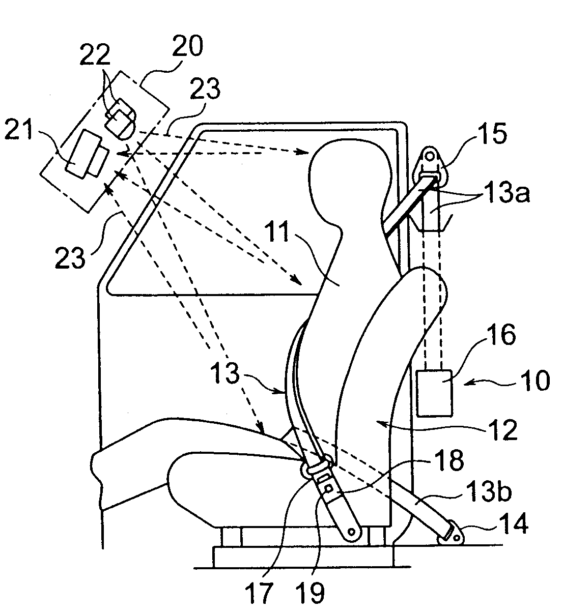
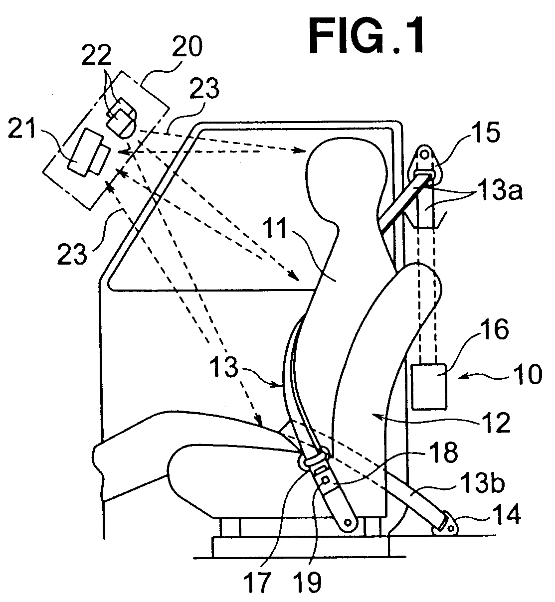
[0018]Now, with reference to FIGS. 1-3, a description will be given about a vehicle occupant detection apparatus in accordance with an embodiment of the present invention. For example, this vehicle occupant detection apparatus of the present invention will be described as constructed to take images of a vehicle occupant (driver) 11 seated in a driver seat. However, it should be noted that the same structural arrangements are provided for detection of another vehicle occupant seated in another seat of the vehicle.

[0019]FIG. 1 is a side view showing the embodiment of the vehicle occupant detection apparatus provided with respect to the vehicle occupant seated in the driver seat; more specifically, FIG. 1 shows, from one side of the vehicle, the vehicle occupant 11 seated in the driver seat. Belt (webbing) 13 of a seat belt apparatus 10 is worn around the vehicle occupant 11 seated in the driver seat 12. The seat belt apparatus 10 restrains the body of the vehicle occupant 11 to the se...


PUM


Abstract

A vehicle occupant detection apparatus includes an image pickup device for imaging an area including a position of a vehicle occupant within a vehicle compartment, a light emitting element for emitting auxiliary light into the compartment that includes the imaging area of the pickup device, and a storage section for storing imaging information provided by the pickup device. The vehicle occupant detection apparatus further including a comparison section for comparing imaging information provided through further imaging by the pickup device and the imaging information stored in the storage section, to provide a difference between the imaging information provided through the further imaging and the stored imaging information, and an abnormality determination section for determining abnormality of the imaging information on the basis of the image information difference.

Description

FIELD OF THE INVENTION[0001]The present invention relates generally to vehicle occupant detection apparatus, and more particularly to an improved vehicle occupant detection apparatus which acquires images of a vehicle occupant via an image pickup device and forestalls a functional failure of the apparatus by monitoring an operating state of the image pickup device.BACKGROUND OF THE INVENTION[0002]The vehicle occupant detection apparatus are apparatus designed to detect a vehicle occupant, such as a driver, present within a vehicle compartment. In these vehicle occupant detection apparatus, an image pickup device, such as a CMOS camera, is installed, for example, on or near a rearview mirror provided on a front upper edge portion of the vehicle compartment, to detect and monitor a vehicle occupant. Today, such vehicle occupant detection apparatus are used to activate a vehicle occupant protection apparatus installed on a vehicle seat in order to protect a vehicle occupant. These vehi...

Claims


Application Information

Patent Timeline
Patent Type & Authority Applications(United States)
IPC IPC(8): B60Q1/00G06K9/00G06V10/141
CPCG06K9/00362G06K9/00832B60R21/01538B60R21/01534G06K9/2027G06V40/10G06V20/59G06V10/141
Inventor ODATE, SHOTAROSUZUKI, YOSHITAKA
Owner HONDA MOTOR CO LTD
Learn More