
LED Lamp Suitable as a Replacement for Fluorescent Lamp in Vending Machines

a technology of led lamps and fluorescent lamps, which is applied in the direction of lighting support devices, light source combinations, instruments, etc., can solve the problems of inefficient conventional ballasts, lamps that cannot meet the requirements, and difficult to view the products to be vended, and achieve the effect of high energy efficiency, built-in flashing and sequencing ability

Active Publication Date: 2008-04-24
ELLENBY TECH
View PDF26 Cites 185 Cited by
  • Summary
  • Abstract
  • Description
  • Claims
  • Application Information

AI Technical Summary

Benefits of technology

[0010]The present invention is intended to provide an LED based replacement for fluorescent lamps, providing diffused light, and operable with existing fluorescent lamp ballasts and directly compatible with existing lamp sockets, or without such preexisting connections and power supplies, as a full replacement for other types of light sources. The lamp assembly of the present invention operates with high energy efficiency on low voltage and includes a control circuit having communications link, as well as remote and wireless control. The lamp assembly of the present invention is dimmable, has built in flashing and sequencing ability as well as control of the color of the light produced. In order to accommodate many installation options, the assembly of the present invention provides a mechanically interconnecting LED based lamp to allow multiple length lamps to be created from a standard smaller size unit. Other features and advantages of the present invention are described further below and will be readily apparent by reference to the following detailed description and accompanying drawings.

Problems solved by technology

The use of incandescent or even LED lights are generally not used in vending machines as having consumers look into these light sources is uncomfortable and tends to be blinding, which would make viewing the products to be vended more difficult.
Without the exception, these lamps would not meet the requirements due to the levels of mercury used in the manufacturing and required for the operation of these lamps.
Each of these has presented challenges and problems which still exist and are particularly notable in applications serviced by untrained personnel such as in vending machines.
The conventional ballasts are inefficient.
Electronic ballast are more efficient but considerably more expensive.
However, they have been associated with a number of quality problems.
These range from the annoying flashing of fluorescent lamps as they age and cannot correctly power on, to arcing at the lamp sockets especially when lamps are not correctly inserted resulting in the potential for fire.
Fluorescent lamps implode when broken, shattering glass and the environmentally unfriendly elements housed within the lamps.
Standard fluorescent lamps emit light in 360 degrees which results in wasted energy or the requirement for reflectors to direct the light where needed.

Method used


Image

  • LED Lamp Suitable as a Replacement for Fluorescent Lamp in Vending Machines
  • LED Lamp Suitable as a Replacement for Fluorescent Lamp in Vending Machines
  • LED Lamp Suitable as a Replacement for Fluorescent Lamp in Vending Machines

Examples


Embodiment Construction

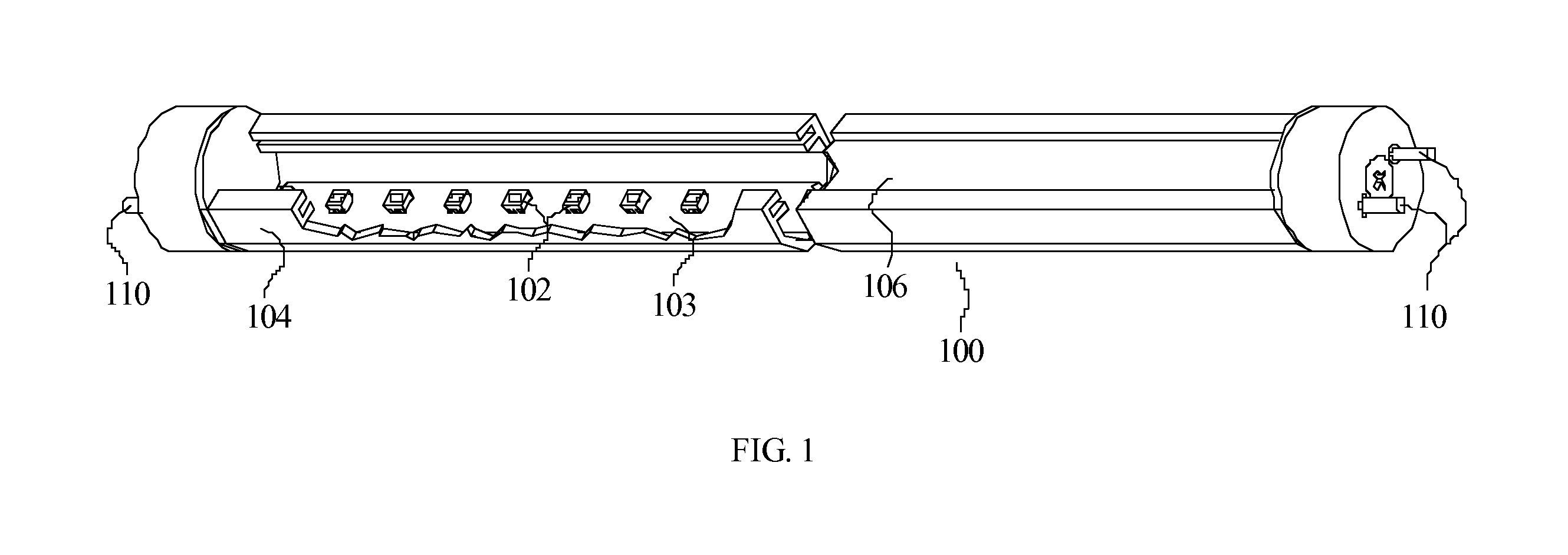
[0020]Referring to FIG. 1, a perspective view, 100, of a presently preferred embodiment of the current invention is shown. An array of white LEDs, 102, are mounted to a printed circuit board, 103, that is then mounted to a metal extrusion, 104. A natural translucent white polystyrene lens, 106, is used to cover the LEDs and act as a diffusing lens. The assembly is terminated on both sides with pin terminals, 110, suitable to mount into standard fluorescent sockets. This allows standard fluorescent bulbs to be replaced by the LED lamp designed for this purpose and described in detail below. The terminals at the end of each of ends of the fluorescent lamp replacement assembly can be adjusted so the orientation of the lamp in the sockets is adjustable. This is best shown in FIG. 2. By positioning the end terminals of the LED lamp, the light output from the lamp can be directed in any position in increments determined by the positioning wheel, 120a and 120b, from the standard mounting p...


PUM

PropertyMeasurementUnit
voltageaaaaaaaaaa
inductanceaaaaaaaaaa
voltageaaaaaaaaaa

Abstract

The present invention is an efficient, long life alternative to conventional vending machine fluorescent lamp light sources that provides added control capabilities. More specifically, the present invention provides reduced energy use, improved safety, extended life, and allows attention-getting use of the machine lighting.

Description

FIELD OF THE INVENTION[0001]The present invention relates to providing an efficient, long life alternative to conventional light sources that provides added value control capabilities. More specifically, the present invention can be used as a fluorescent lamp alternative in a vending machine to reduce energy use, improve safety, extend life, and allow attention getting use of the machine lighting. Additionally, by adding intelligence (in the form of a control circuit) to the light source, the machine controller can accommodate specific energy and lighting needs through simple control interfaces.BACKGROUND OF THE INVENTION[0002]The current trends toward increased efficiency, environmental friendliness, and higher quality longer life products makes the transition to LED based lighting more and more prevalent. The use of LED lighting in automobile lights, traffic lights, and even incandescent light replacements is a growing trend. There are a number of reasons the use of LED lights has...

Claims


Application Information

Patent Timeline
Patent Type & Authority Applications(United States)
IPC IPC(8): F21V21/00H05B44/00
CPCF21K9/00F21K9/17F21Y2101/02G07F9/10H05B33/083Y02B20/386G07F9/023F21Y2103/003F21Y2103/10F21Y2115/10F21Y2113/17Y10T29/49002F21K9/278H05B45/48Y02B20/30H05B45/20H05B47/19H05B45/10H05B45/325H05B45/3725H05B45/3578F21V23/06F21V33/008F21W2131/403F21V23/009F21Y2113/13F21V23/02
Inventor DOBBINS, BOB M.FRONTINO, LOUIS J.REGER, PHILIP R.MASON, PAUL L.
Owner ELLENBY TECH
Learn More