Method and system for verifying connectivity of multi-segment pseudo-wires by tracing

a pseudo-wire and multi-segment technology, applied in the field of network management and service provisioning, can solve the problems of inability to easily pinpoint the point of failure, time-consuming, unusable, etc., and achieve the effect of confirming the connectivity of the second segmen

Active Publication Date: 2008-04-24
ALCATEL LUCENT SAS
View PDF6 Cites 51 Cited by
  • Summary
  • Abstract
  • Description
  • Claims
  • Application Information

AI Technical Summary

Benefits of technology

[0019]The method may further include, if there is a second segment: (c) sending a second echo request message from the first provider edge device to the third provider edge device; and, (d) receiving a second echo reply message from the third provider edge device in response to the second echo request message, the second echo reply message: confirming connectivity of the second segment; indicating whether there is a third segment in the multi-segment pseudo-wire between the third provider edge device and a fourth provider edge device; and, if there is a third segment, including information pertaining to the third segment. The first provider edge device may have information pertaining to the first segment. The echo request message may include the information pertaining to the first segment. The second echo request message may include the information pertaining to the second segment. The packet switched network may be a multiprotocol label switching (“MPLS”) network. The information pertaining to the first and second segments may include a type-length-value (“TLV”) for a pseudo-wire forwarding equivalence class (“FEC”). The indicating whether there is a second segment in the multi-segment pseudo-wire between the second provider edge device and a third provider edge device may be facilitated by at least one of: the echo reply message including the information pertaining to the second segment; and, first and second return codes, wherein the first return code indicates that the second segment does exist, and wherein the second return code indicates that the second segment does not exist. The packet switched network may include first and second packet switched networks, wherein the first and second segments may be in the first and second packet switched networks, respectively, and wherein the first and second packet switched networks are controlled by first and second service providers, respectively. And, the second provider edge device may be a kth provider edge device, the third provider edge device may be a (k+1)th provider edge device, the first segment may be a (k−1)th segment of n segments of the multi-segment pseudo-wire between the first provider edge device and the kth provider edge device, the second segment may be a kth segment of the n segments of the multi-segment pseudo-wire between the kth provider edge device and the (k+1)th provider edge device, k and n are integers, k is less than or equal to n, and further comprising repeating steps (a) and (b) for k=3 to n.

Problems solved by technology

However, for new MS-PW services, there is currently no effective method to easily pinpoint the point of failure and verify the end-to-end connectivity of a MS-PW.
In particular, one problem with present MS-PW networks is that the control plane of the ingress node (i.e., the T-PE) of the MS-PW does not have access to the necessary information pertaining to the next segment of the MS-PW in order to format a VCCV echo request (or ping) and to allow for the successful validation of the echo request at the next segment of the MS-PW.
While an operator of the network can manually perform a VCCV ping for each individual segment of the MS-PW one at a time, this is time consuming, not user-friendly, and requires the operator to have detailed knowledge of each segment of the whole MS-PW.
In addition, such a manual approach may not even be possible if the operator does not have access to all the segments of the MS-PW (e.g., if the MS-PW spans the PSNs of different SPs).

Method used


Image

  • Method and system for verifying connectivity of multi-segment pseudo-wires by tracing
  • Method and system for verifying connectivity of multi-segment pseudo-wires by tracing
  • Method and system for verifying connectivity of multi-segment pseudo-wires by tracing

Examples


Embodiment Construction

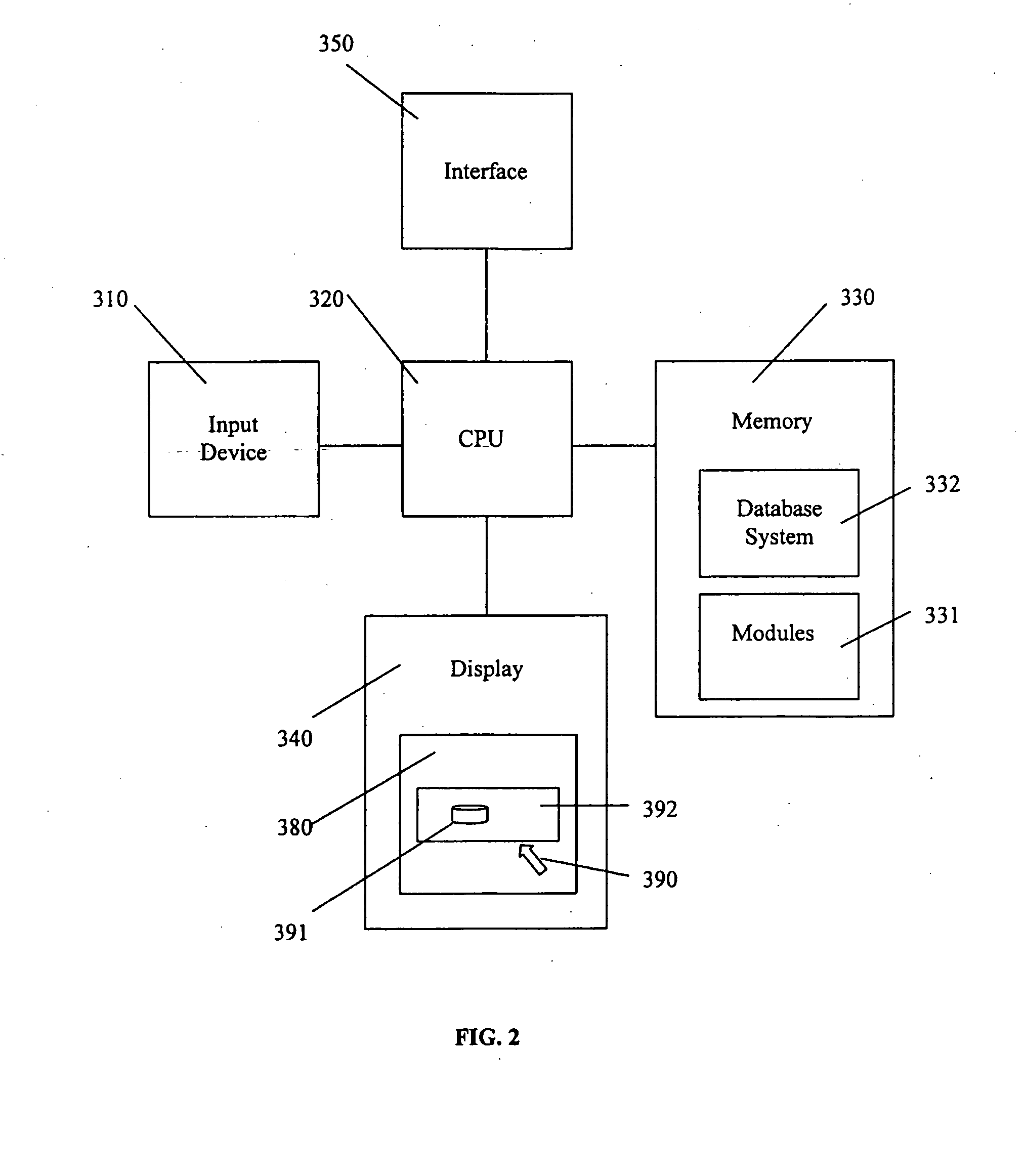
[0026]In the following description, details are set forth to provide an understanding of the invention. In some instances, certain software, circuits, structures and techniques have not been described or shown in detail in order not to obscure the invention. The term “data processing system” is used herein to refer to any machine for processing data, including the network elements and network management systems described herein. The present invention may be implemented in any computer programming language provided that the operating system of the data processing system provides the facilities that may support the requirements of the present invention. Any limitations presented would be a result of a particular type of operating system or computer programming language and would not be a limitation of the present invention. The present invention may also be implemented in hardware.

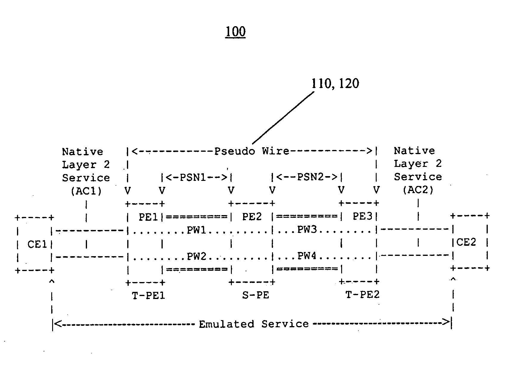
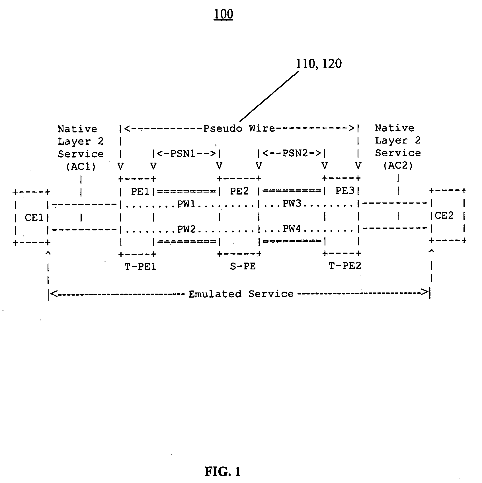
[0027]FIG. 1 is a block diagram illustrating a multi-segment pseudo-wire based communications network 100...


PUM


Abstract

A method for testing connectivity of a multi-segment pseudo-wire in a packet switched network, the method comprising: (a) sending an echo request message from a first provider edge device to a second provider edge device for a first segment of the multi-segment pseudo-wire between the first provider edge device and the second provider edge device; and, (b) receiving an echo reply message from the second provider edge device in response to the echo request message, the echo reply message: confirming connectivity of the first segment; indicating whether there is a second segment in the multi-segment pseudo-wire between the second provider edge device and a third provider edge device; and, if there is a second segment, including information pertaining to the second segment.

Description

FIELD OF THE INVENTION[0001]This invention relates to the field of network management and service provisioning, and more specifically, to a method and system for verifying connectivity for multi-segment pseudo-wires in packet switched networks.BACKGROUND OF THE INVENTION[0002]Multiprotocol label switching (“MPLS”) provides a mechanism for engineering network traffic patterns in which short labels are assigned to network packets that describe how to forward them through a network (e.g., a packet switched network (“PSN”)). In a MPLS network, a node, switch or router which supports MPLS is generally known as a label switching router (“LSR”) and a LSR at the edge (ingress or egress) of the MPLS network is generally known as a label edge router (“LER”).[0003]In general, as a data frame of a connectionless network layer protocol (e.g., the Internet Protocol (“IP”)) travels from a source node to a destination node it travels from one node to the next through the network. Each node makes an...

Claims


Application Information

Patent Timeline
Patent Type & Authority Applications(United States)
IPC IPC(8): H04J3/14H04J1/16H04L12/56
CPCH04L43/0811H04L45/50H04L43/10
Inventor HUA, MICHAEL NGHIAAISSAOUI, MUSTAPHAGRIGORIU, TIBERIU
Owner ALCATEL LUCENT SAS
Why Eureka
Try Eureka