Signal Separating Device and Signal Separating Method

a signal separation and signal technology, applied in multi-frequency code systems, multi-frequency communication, diversity/multi-antenna systems, etc., can solve the problems of large power consumption and large calculation load required for signal detection, and achieve the effect of improving signal detection accuracy

Inactive Publication Date: 2008-04-24
NTT DOCOMO INC
View PDF16 Cites 40 Cited by
  • Summary
  • Abstract
  • Description
  • Claims
  • Application Information

AI Technical Summary

Benefits of technology

[0038] According to the present invention, signal detection accuracy can be improved in a receiver for the communications system complying with the MIMO scheme.

Problems solved by technology

But, there is a problem in that calculation load required for signal detection becomes large since it is necessary to calculate the squared Euclidean distance many times. For example, assuming that four transmission signals are transmitted from four transmission antennas using a 16QAM modulation scheme.
Further, when the calculation load is large, power consumption becomes large, which is especially disadvantageous for a small mobile terminal.

Method used


Image

  • Signal Separating Device and Signal Separating Method
  • Signal Separating Device and Signal Separating Method
  • Signal Separating Device and Signal Separating Method

Examples


first embodiment

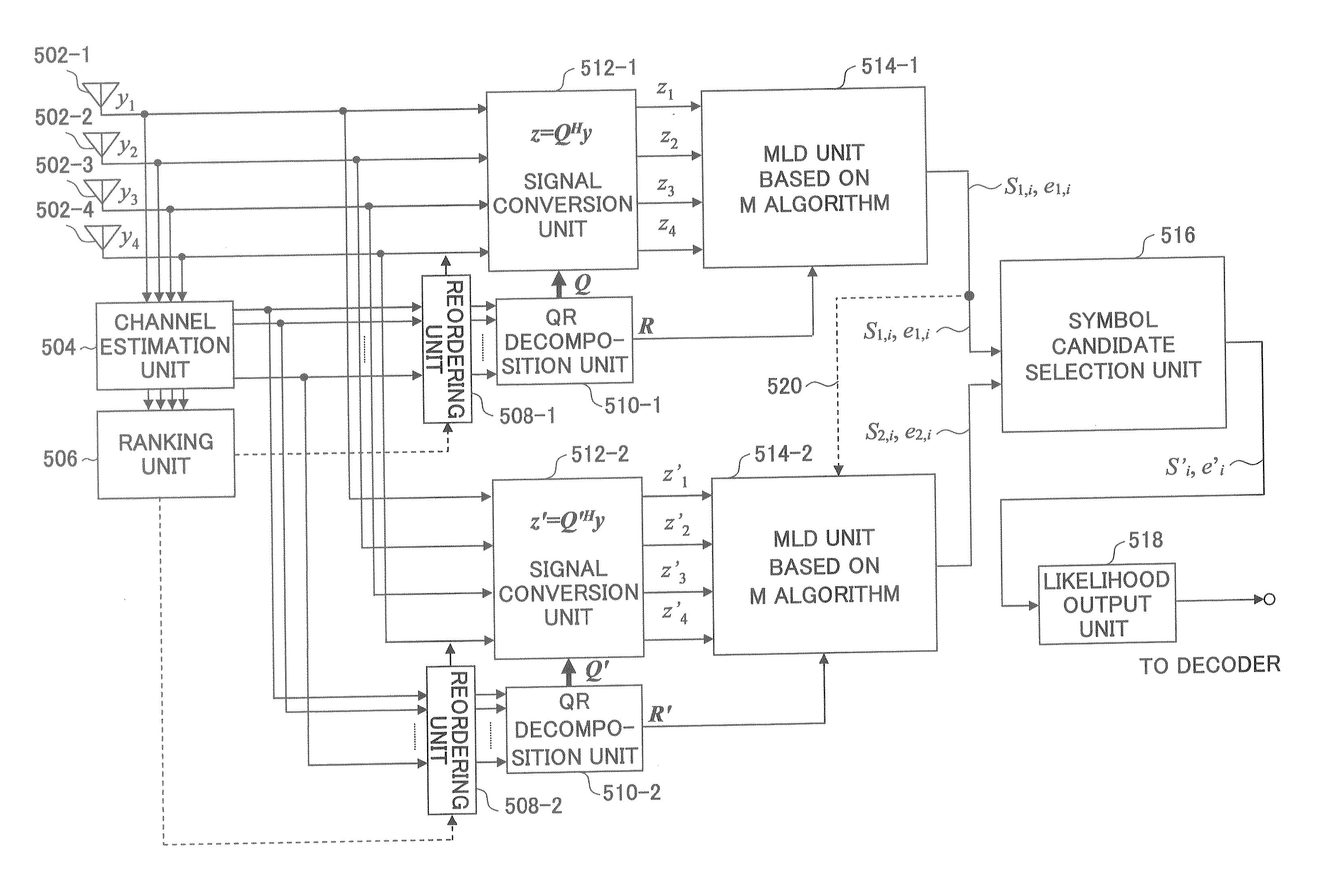
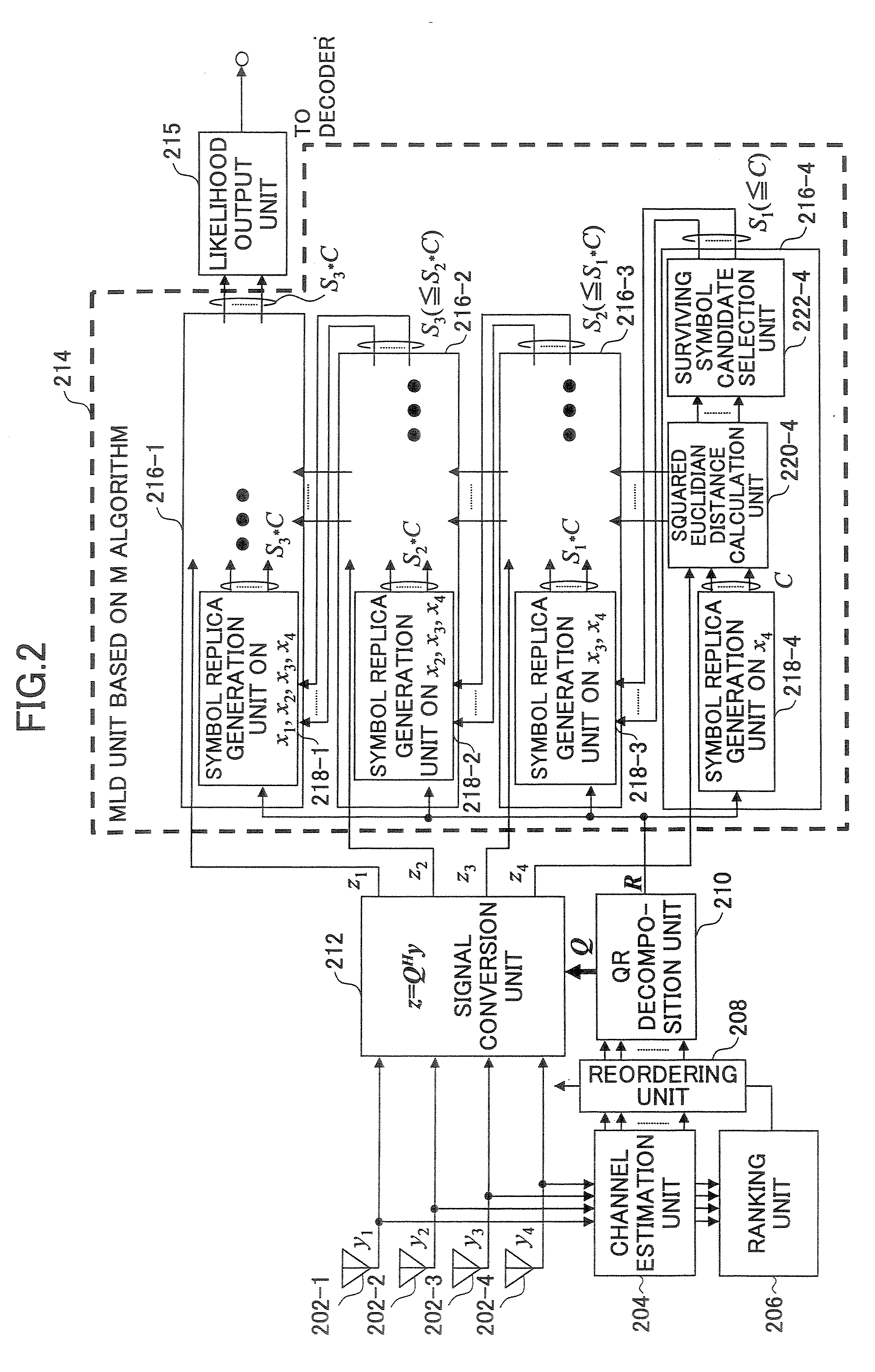
[0054]FIG. 5 shows a partial block diagram of a receiver for performing the signal detection method according to an embodiment of the present invention. For the sake of simplicity, it is assumed that four transmission signals x=(x1 x4)T are transmitted from the four transmission antennas respectively with the 16QAM modulation scheme. But, the number of antennas and the modulation scheme and the like are not limited to these. The receiver includes a plurality of receiving antennas 502-1, 502-2, 502-3 and 502-4, a channel estimation unit 504, a ranking unit 506, reordering units 508-1 and 2, OR decomposition units 510-1 and 2, signal conversion units 512-1 and 2, maximum likelihood determination units 514-1 and 2, symbol candidate selection unit 516 and a likelihood output unit 518. Since each of the maximum likelihood determination units 514-1 and 2 includes configuration and functions similar to those of the maximum likelihood determination unit 214 shown in FIG. 2, detailed descrip...

second embodiment

[0079] Although maximum likelihood determination on the first order is performed completely independently of maximum likelihood determination on the second order in the first embodiment, a part of determination results of one side may be incorporated in determination calculation in another side. For example, determination results on the first and second transmission signals x1 and x2 in maximum likelihood determination results on the first order shown in FIG. 5 may be used for maximum likelihood determination on the second order. Information is provided from the maximum likelihood determination unit 514-1 to the maximum likelihood determination unit 514-2 via a signal line 520.

[0080] As shown in FIG. 8, symbol candidates (enclosed by a dotted line frames of the first and second transmission signals x1 and x2 included in determination results S1,i based on the first order are used for maximum likelihood determination based on the second order. In the example shown in the figures ins...


PUM


Abstract

A signal detection apparatus improving signal detection accuracy in a receiver for communications system complying with the MIMO scheme. The signal detection apparatus detects transmission signals sent from transmission antennas based on received signals received by receiving antennas. The apparatus includes: a first determination mechanism for determining symbol candidates of the transmission signals in sequence based on the QRM-MLD method using the received signals arranged in first order; a second determination mechanism for determining symbol candidates of the transmission signals in sequence based on the QRM-MLD method using the received signals arranged in second order that is different from the first order; and an output mechanism for outputting symbol candidates and likelihood of the transmission signals based on determination results of at least the first and the second determination mechanisms.

Description

TECHNICAL FIELD [0001] The present invention generally relates to a technical field of wireless communications of a Multiple-Input Multiple-Output (MIMO) scheme. More particularly, the present invention relates to a signal detection apparatus and a signal detection method used in a receiver for the MIMO scheme. BACKGROUND ART [0002] In this kind of technical fields research and development are being promoted for realizing large-capacity high-speed information communications coming after current and next-generation techniques. For example, in addition to a Single-Input Single-Output (SISO) scheme, researches are being promoted for a Single-Input Multiple-Output (SIMO) scheme, a Multiple-Input Single-Output (MISO) and the Multiple-Input Multiple-Output (MIMO) scheme and the like from the viewpoint of increasing communications capacity. [0003]FIG. 1 shows an outline of a communications system of the MIMO scheme including a transmitter 102 and a receiver 104. In the MIMO scheme, differe...

Claims


Application Information

Patent Timeline
Patent Type & Authority Applications(United States)
IPC IPC(8): H04L27/28H04J99/00
CPCH04B7/0413H04L25/03006H04L2025/03528H04L2025/03426H04L25/067
Inventor MAEDA, NORIYUKIHIGUCHI, KENICHIKAWAI, HIROYUKISAWAHASHI, MAMORU
Owner NTT DOCOMO INC
Why Eureka
Try Eureka