Signal detection circuit, data transmission controller and electronic equipment

A control device and data transmission technology, applied in electronic switches, electrical components, pulse processing, etc., can solve the problems of high frequency characteristics, high cost, and difficulty in detecting small-amplitude signal reception, and achieve low-cost effects

Inactive Publication Date: 2004-12-22
SEIKO EPSON CORP
View PDF0 Cites 0 Cited by
  • Summary
  • Abstract
  • Description
  • Claims
  • Application Information

AI Technical Summary

Problems solved by technology

Therefore, when a signal detection circuit is constituted by a conventional envelope detection circuit, there is a problem that a high frequency characteristic is required even if a currently available expensive micro-processing is used.
In addition, such an envelope detection circuit is difficult to detect the reception of small amplitude signals

Method used


Image

  • Signal detection circuit, data transmission controller and electronic equipment
  • Signal detection circuit, data transmission controller and electronic equipment
  • Signal detection circuit, data transmission controller and electronic equipment

Examples


Embodiment Construction

[0063] Hereinafter, preferred embodiments of the present invention will be specifically described with reference to the drawings.

[0064] 1. Signal detection circuit

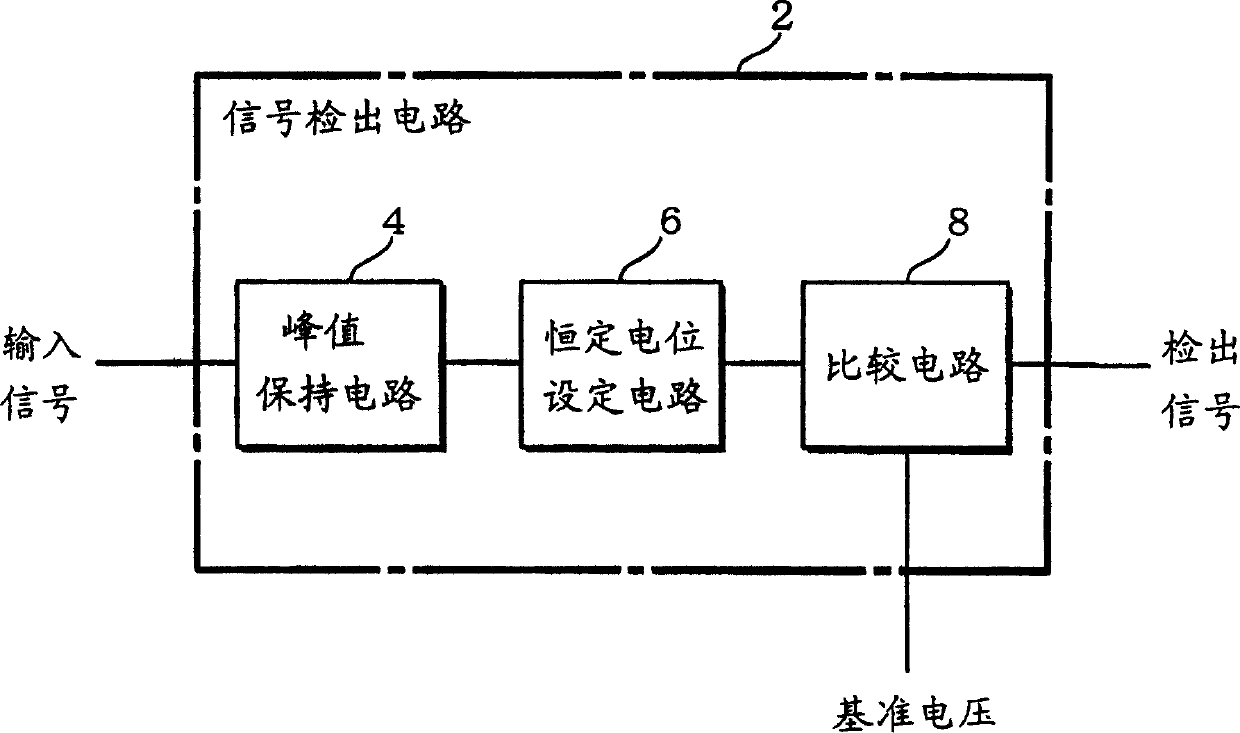
[0065] FIG. 1 shows a schematic structure diagram of the signal detection circuit of this embodiment.

[0066] The signal detection circuit 2 includes a peak hold circuit 4 , a constant potential setting circuit 6 , and a comparison circuit 8 .

[0067] The peak hold circuit 4 holds the peak value of the input signal at a given node.

[0068] The constant potential setting circuit 6 returns the potential of the given node which changes when the peak value is held by the peak hold circuit 4 to a given constant potential. At this time, the constant potential setting circuit 6 can return to a constant potential with a time constant larger than the potential change of the holding peak value. Here, the potential change due to the hold peak is the potential change caused by the peak hold circuit 4 . More specific...


PUM


Abstract

There is provided a signal detection circuit capable of detecting a signal at a high speed having small amplitude, and a data transfer control device and electronic equipment using the same. The signal detection circuit includes a peak hold circuit, a constant potential setting circuit, and a comparison circuit. The peak hold circuit holds a peak value of an input signal at a given node. The constant potential setting circuit always returns the potential at the given node changed by holding the peak value by the peak hold circuit to a constant potential at a time constant greater than the potential change caused by holding the peak value. The comparison circuit compares the potential at the node at which the peak value is held and which is slowly returned to the constant potential with a given reference level, and outputs the comparison result as a detection signal.

Description

technical field [0001] The present invention relates to a signal detection circuit, a data transmission control device and electronic equipment using the signal detection circuit. Background technique [0002] In recent years, USB (Universal Serial Bus) has attracted more and more attention as an interface specification for connecting personal computers and peripheral devices (electronic devices in a broad sense). The USB has the advantages of connecting peripheral devices such as mice, keyboards, and printers that were previously connected with connectors of different specifications with connectors of the same specification, and at the same time can realize the advantages of so-called plug and play and hot plugging. [0003] On the other hand, this USB has a problem that the transmission speed is slower than IEEE1394, which is also attracting attention as a serial bus interface standard. [0004] Therefore, attention has been drawn to study the USB 2.0 specification which ...

Claims


Application Information

Patent Timeline
Patent Type & Authority Patents(China)
IPC IPC(8): G06F3/16H03K5/08H03K5/1532H04L25/02
CPCH03K5/082H03K5/1532
Inventor 中田章
Owner SEIKO EPSON CORP
Why Eureka
Try Eureka