Single-step fiber grinding process and apparatus

a fiber and process technology, applied in the direction of grinding drives, manufacturing tools, instruments, etc., can solve the problems of complex multi-step grinding process, inability to provide optical fibers with asymmetric fiber end faces or microlenses, complex construction and operation of the entire system, etc., and achieve the effect of less complicated construction

Inactive Publication Date: 2008-04-24
NAT SUN YAT SEN UNIV
View PDF5 Cites 10 Cited by
  • Summary
  • Abstract
  • Description
  • Claims
  • Application Information

AI Technical Summary

Benefits of technology

[0013] Another object of the invention is to provide a novel fiber grinding apparatus that has less complicated construction and that can produce a substantially cone-shaped end face having a non-circular cross section by employing a single grinding step.

Problems solved by technology

Since the polishing system 2 employs three step motors which require different control parameters, the construction and operation of the entire system are complicated.
In addition, while the polishing system 2 can form the optical fiber end face into a hemisphere, a circular cone, a wedge shape, or a quadrangular pyramid shape, it is unable to provide an optical fiber with an asymmetric fiber end face or microlens that has good coupling with a high power laser having a high aspect ratio.
The multi-step grinding process is complicated due to the use of multiple grinding steps.
Furthermore, because the multiple grinding steps are employed, it is difficult to have control over small offset of fiber microlens (i.e., the eccentricity between the center of the optical fiber and the microlens) to form reproducible elliptical fiber end faces or fiber microlenses, thus resulting in low yield fabrication.

Method used


Image

  • Single-step fiber grinding process and apparatus
  • Single-step fiber grinding process and apparatus
  • Single-step fiber grinding process and apparatus

Examples


Embodiment Construction

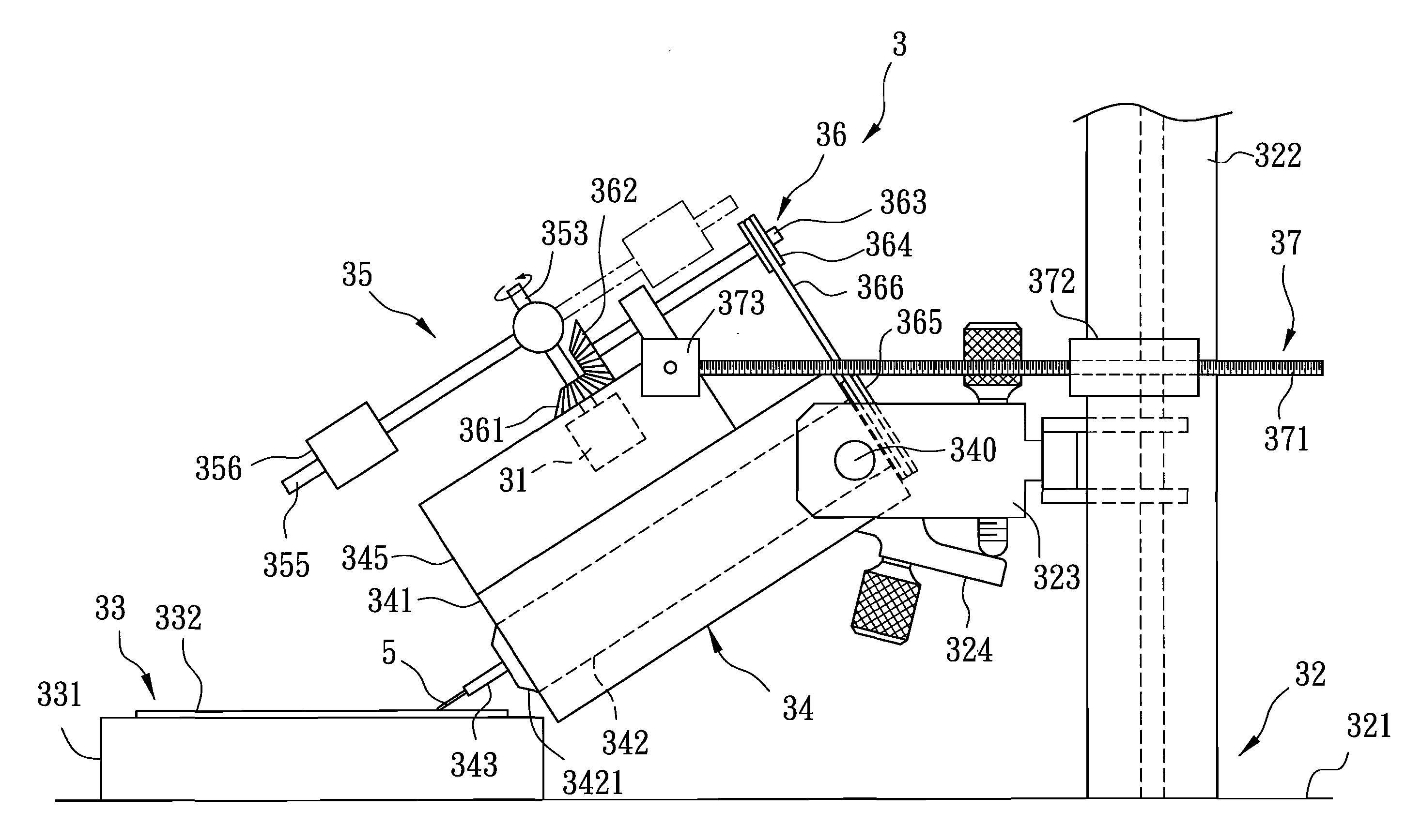
[0029] Referring to FIGS. 4, 5 and 6, a fiber grinding apparatus 3 embodying the present invention includes a rotating unit 31, a support 32, a grinder 33, a fiber carrier 34 adapted to carry an optical fiber 5, a contact pressure changing unit 35, a transmission unit 36, and a counter-balancing unit 37.

[0030] The support 32 has a base seat 321, an upstanding frame 322, and a bracket 323 projecting from the upstanding frame 322.

[0031] The grinder 33 has a grinder seat 331 disposed on the base seat 321, and a grinding film 332 mounted on the grinder seat 331 to contact an end of the optical fiber 5.

[0032] The fiber carrier 34 has a housing 341, a ferrule holder 342 mounted rotatably within the housing 341 for rotation about an inclined axis (X) (shown in FIG. 6), and a ferrule 343 inserted in the ferrule holder 342 and receiving the optical fiber 5 along the inclined axis (X). The ferrule holder 342 extends downwardly and inclinedly along the inclined axis (X), and has a lower end...


PUM

PropertyMeasurementUnit
rotating anglesaaaaaaaaaa

Abstract

A fiber grinding process includes: contacting an end of the optical fiber with a grinding surface in such a manner that a central axis of the optical fiber at the end is inclined to the grinding surface; rotating the optical fiber about the central axis; and changing a contact pressure between the end of the optical fiber and the grinding surface by applying a variable torque while rotating the optical fiber. A substantially cone-shaped end face with a substantially elliptic cross-section may be produced. A fiber grinding apparatus is also disclosed.

Description

CROSS-REFERENCE TO RELATED APPLICATION [0001] This application claims priority of Taiwanese Patent Application No. 95135358, filed on Sep. 25, 2006. BACKGROUND OF THE INVENTION [0002] 1. Field of the Invention [0003] This invention relates to a fiber grinding technique, more particularly, to a fiber grinding process and apparatus that employs a single-step grinding technique to asymmetrically shape an end face of an optical fiber. [0004] 2. Description of the Related Art [0005] Nowadays, optical fibers have been used widely in daily activities of people, for instance, in transmitting images, voices, data, etc. Since optical fibers have the properties of high capacity, high quality and high speed, they have been substituted increasingly for conventional communication cables. [0006] Referring to FIG. 1, a typical optical fiber 1 has a fiber end face 11 and a fiber core 12. The fiber end face 11 determines the coupling efficiency of the optical fiber 1. A high coupling efficiency means...

Claims


Application Information

Patent Timeline
Patent Type & Authority Applications(United States)
IPC IPC(8): B24B1/00
CPCB24B5/14B24B19/226B24B19/16
Inventor TSAI, YING-CHIENLU, YU-KUANLIU, YU-DACHENG, WOOD-HI
Owner NAT SUN YAT SEN UNIV
Why Eureka
Try Eureka