Multi-slit high flow valve
- Summary
- Abstract
- Description
- Claims
- Application Information
AI Technical Summary
Benefits of technology
Problems solved by technology
Method used
Image

Examples
Embodiment Construction
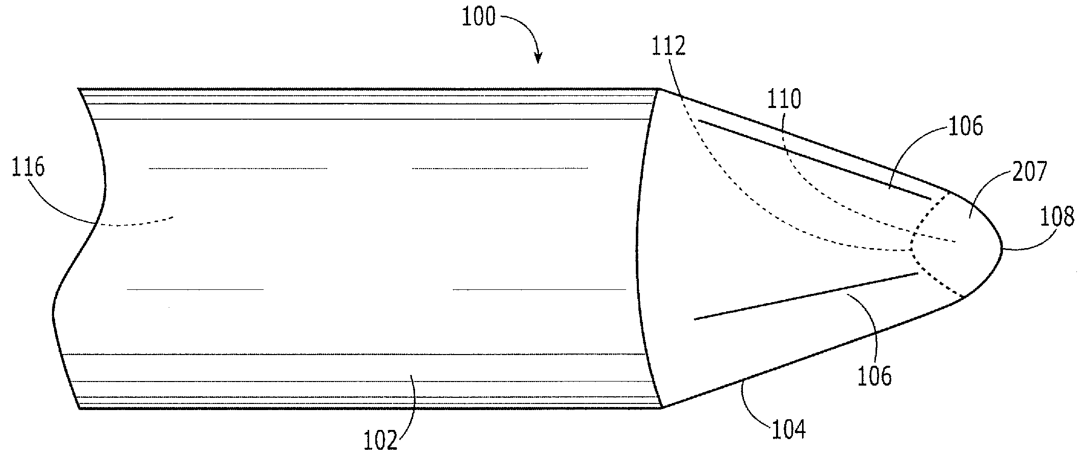
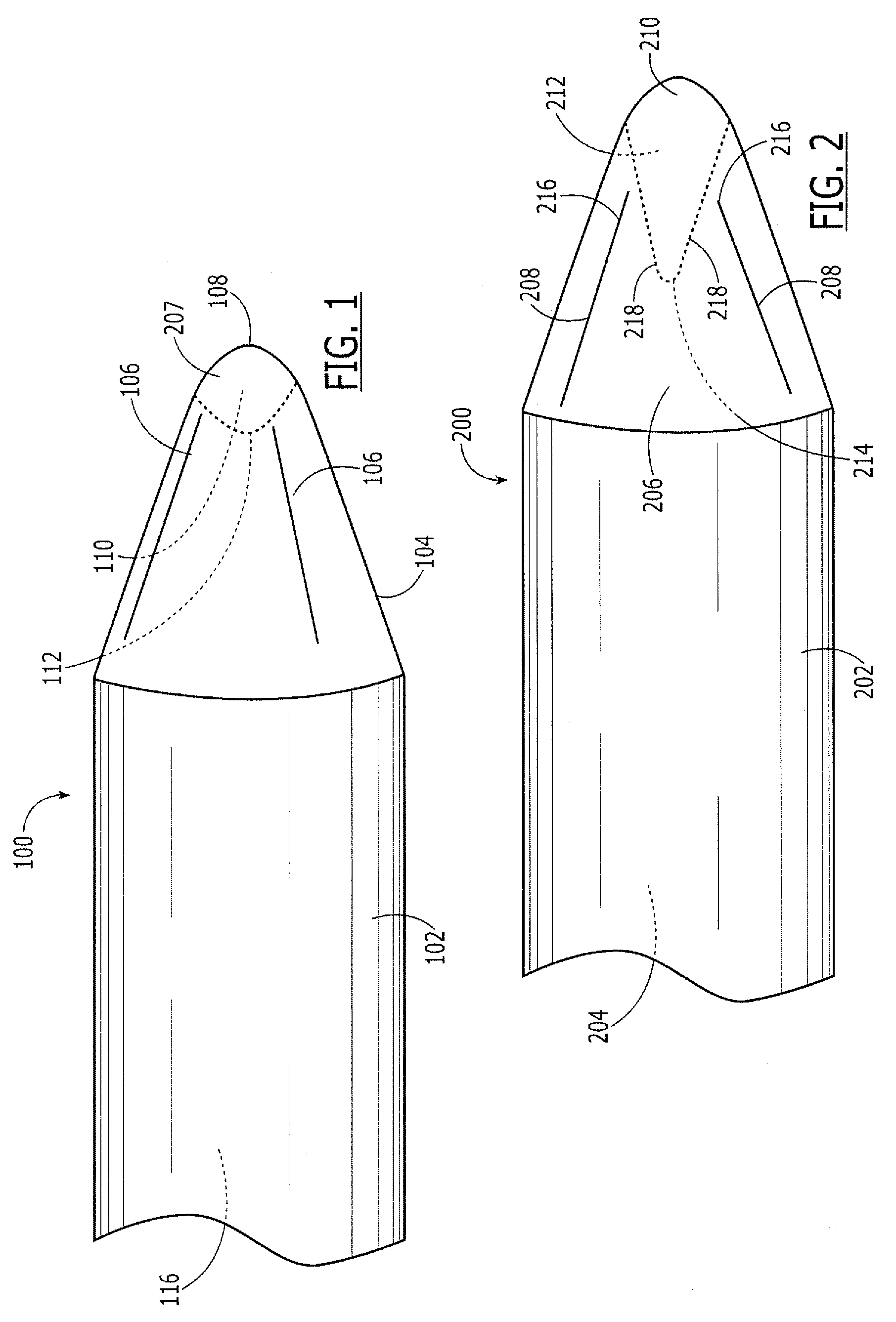
[0008]The present invention may be further understood with reference to the following description and to the appended drawings, wherein like elements are referred to with the same reference numerals. The present invention relates to valves used selectively sealing a proximal end of a catheter and more specifically relates to high flow multi-slit membranes used in catheter valves.
[0009]When an internal shape of a conic valve mirrors the external shape (i.e., the internal space is conic), difficulties may arise when attempting to pass a guidewire through the catheter. The tips of guidewires or other instruments may become trapped in the concave vertex of the valve instead of passing through a slit. According to the exemplary embodiments of the present invention, the internal shape of the cone tip of the valve membrane is modified to divert and direct a guidewire or other instrument inserted therethrough into one of the slits. According to exemplary embodiments of the present invention...
PUM
 Abstract
Description
Claims
Application Information