
Electrode markers and methods of use

Active Publication Date: 2008-04-24
BOSTON SCI SCIMED INC
View PDF99 Cites 122 Cited by
  • Summary
  • Abstract
  • Description
  • Claims
  • Application Information

AI Technical Summary

Benefits of technology

[0009]In treating tissue regions, such as within the lungs, a treatment device may utilize an elongate sheath or shaft having a plurality of markers, rings, bands, or other visual indicators along an outer surface thereof so as to facilitate guidance of the device to effectively and efficiently treat the tissue according to a predetermined axial treatment. Th

Problems solved by technology

This causes widespread variable airflow obstruction which makes it difficult for an asthma sufferer to breathe.
Both of these approaches require repeated and regular use of prescribed drugs, which often present difficulties in patient compliance.
High doses of corticosteroid anti-inflammatory drugs can have serious side effects that require careful management.
The difficulty of avoiding stimulus that triggers asthma is also a common barrier to successful asthma management.
As such, current management techniques are neither completely successful nor free from side effects.
However, in utilizing the treatment devices in a patient, visibility of the energy delivery element, particularly depth perception, within the lung airways may be relatively limited as viewed from an imaging lens of an access device, such as a bronchoscope or endoscope.
Limited visibility combined with a variety of other factors, including airway movement due to patient breathing, coughing, and / or wheezing (tidal motion) as well as movement of the access device, may make it difficult to ensure desired axial treatment of the lung airways with the energy delivery device.
For example, in procedures where a relatively long region of tissue is to be treated (e.g., longer than a length of the energy delivery element), difficulty in ascertaining the amount of tissue being treated may result in over-treatment of the same region or non-treatment of the target region.
Additionally, such conditions may result in slower procedures that increase total procedure time and patient discomfort.

Method used


Image

  • Electrode markers and methods of use
  • Electrode markers and methods of use
  • Electrode markers and methods of use

Examples


Embodiment Construction

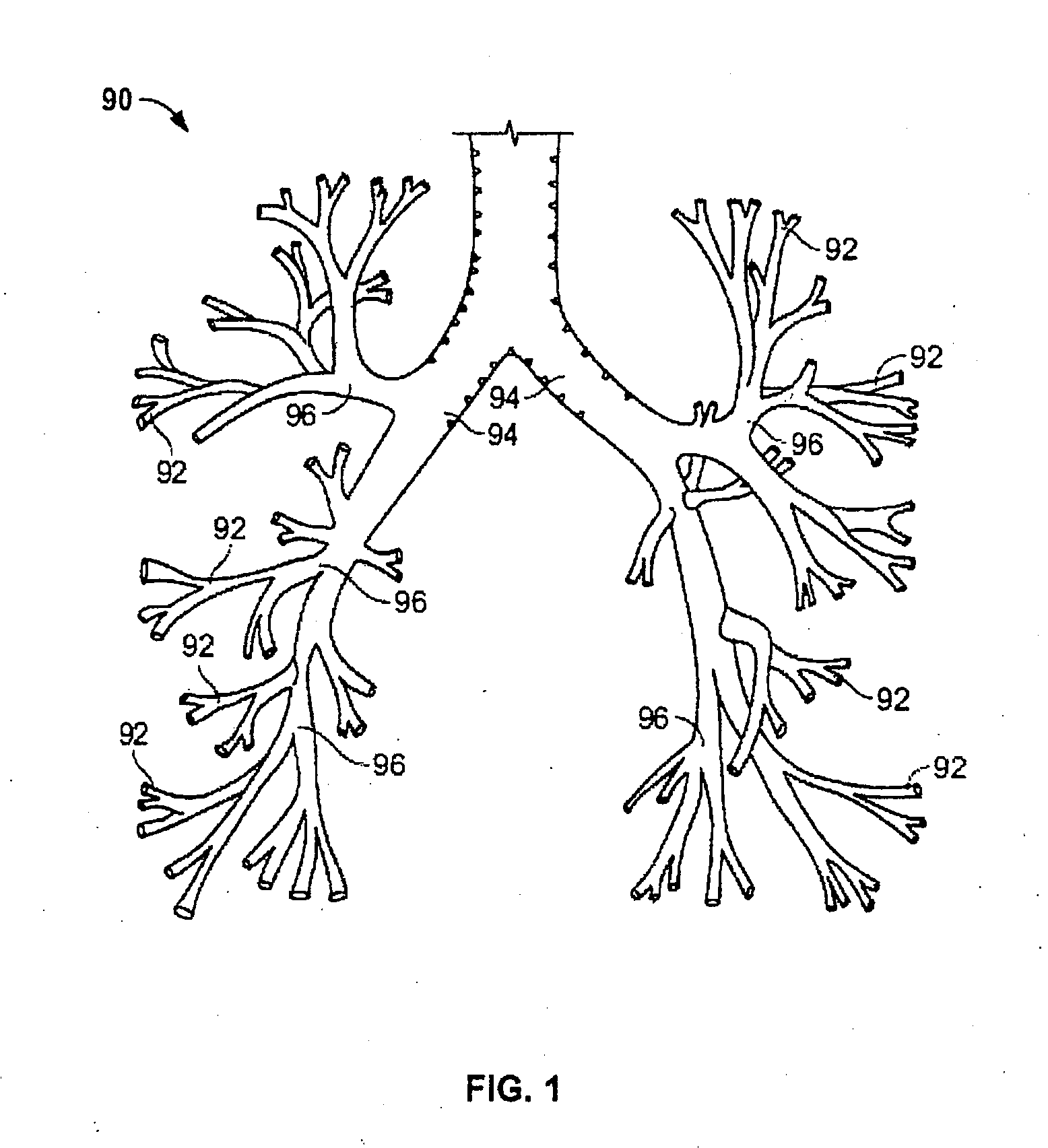
[0031]It will be appreciated that the examples below discuss uses in the airways of the lungs. However, unless specifically noted, the devices and methods described herein are not limited to use in the bronchial passageways. Instead, such devices and methods may have applicability in various parts of the body, such as the upper respiratory tract, trachea, esophagus, urethra, ureter, digestive tract, cardiovascular system, circulatory system, arthroscopic, brain, liver, etc. Moreover, the present invention may be used in various procedures where the benefits of the device are desired.

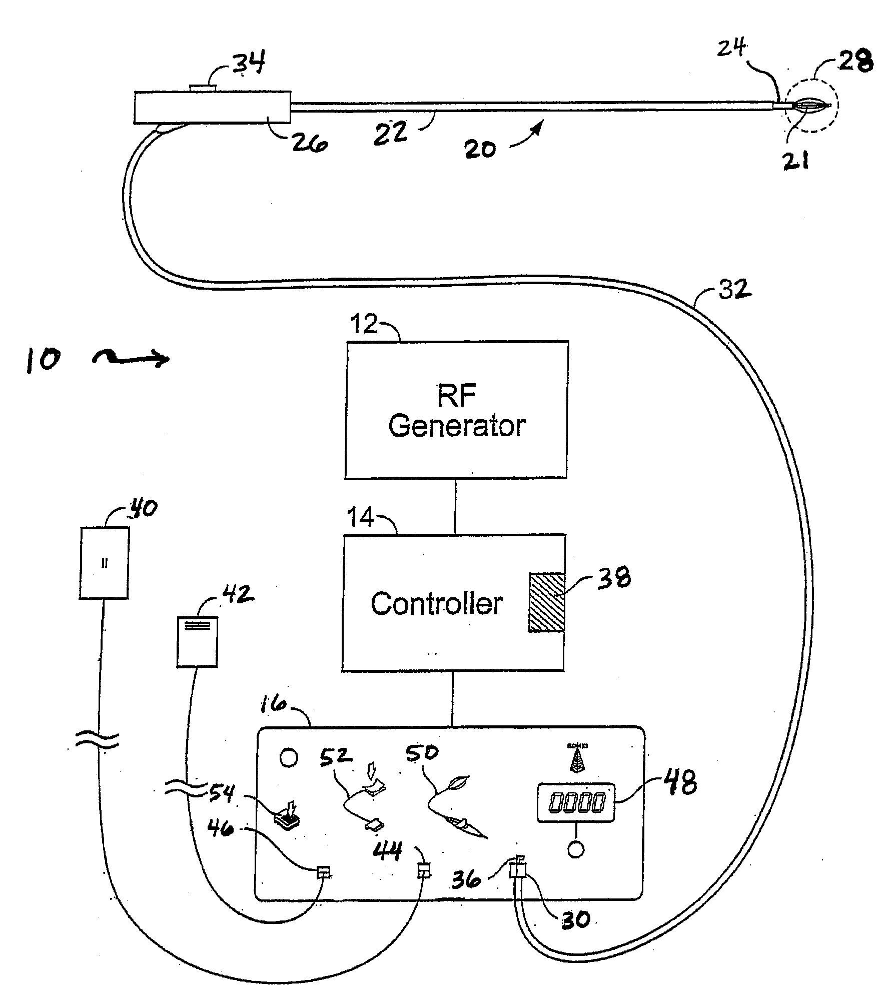
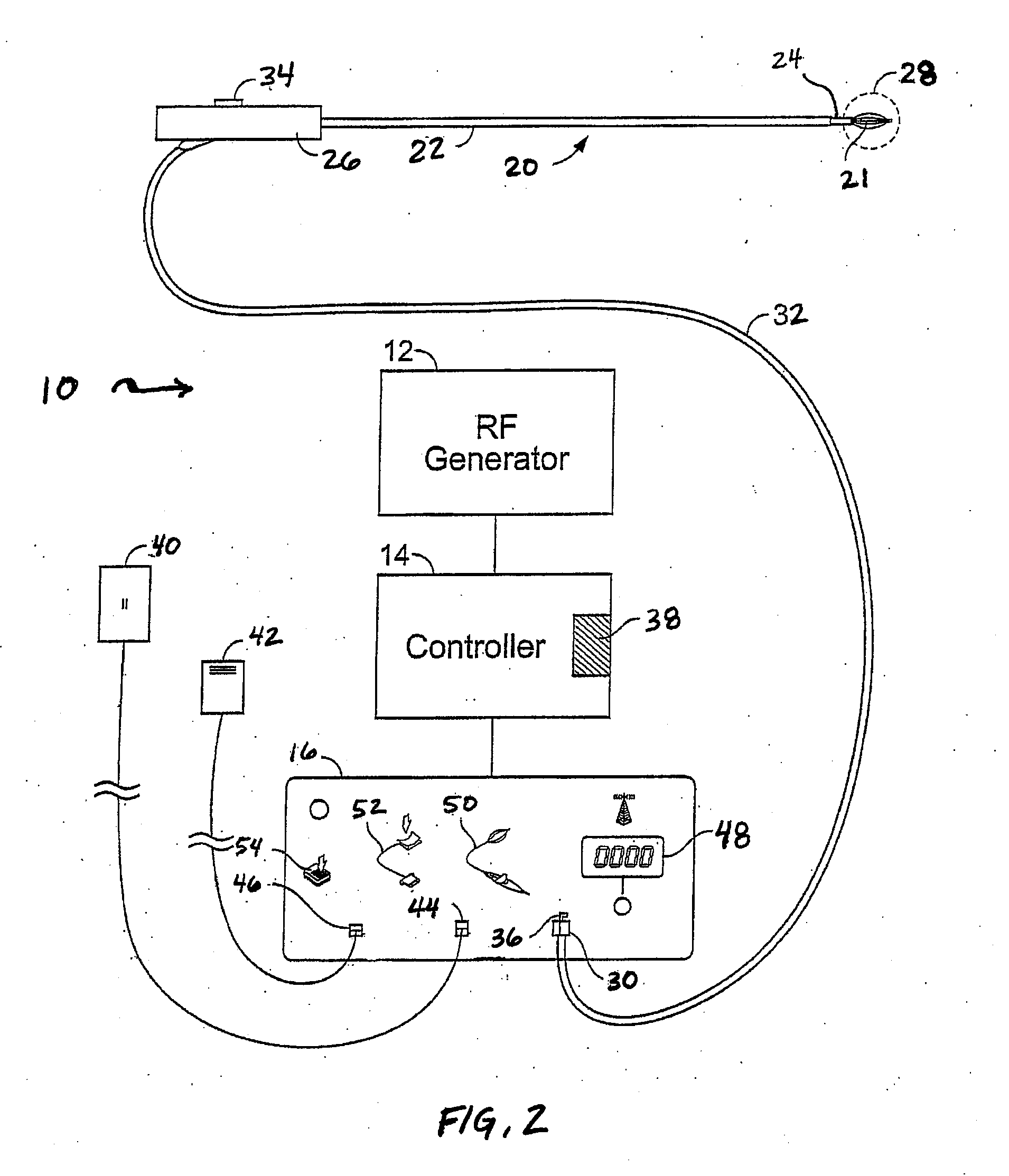
[0032]Generally, in treating tissue regions within the lungs, the treatment device may utilize an elongate body, such as tubular sheath, shaft, or catheter, having a plurality of markers, rings, bands, or other visual indicators (e.g., circular or otherwise) along an outer surface thereof. The plurality of visual indicators facilitate guidance of the device to effectively and efficiently treat the tissue...


PUM


Abstract

An energy delivery device for treating tissue regions in a body conduit, such as a lung airway, may utilize one or more markers, rings, bands, or other visual indicators along an outer surface of the device body. The one or more visual indicators facilitate guidance of the device to effectively and efficiently treat the tissue according to a predetermined axial treatment as well as measure extension of a distal portion of the device, tissue length, and / or treatment length. The predetermined axial treatment may be contiguous, overlapping, or intermittently spaced apart as determined by the marker spacing distance.

Description

BACKGROUND OF THE INVENTION[0001]Asthma is a disease in which bronchoconstriction, excessive mucus production, and inflammation and swelling of airways occur. This causes widespread variable airflow obstruction which makes it difficult for an asthma sufferer to breathe. Asthma is a chronic disorder, primarily characterized by persistent airway inflammation. Asthma is further characterized by acute episodes of additional airway narrowing via contraction of hyper-responsive airway smooth muscle.[0002]Asthma is traditionally managed pharmacologically by: (1) long term control through use of anti-inflammatories and long-acting bronchodilators and (2) short term management of acute exacerbations through use of short-acting bronchodilators. Both of these approaches require repeated and regular use of prescribed drugs, which often present difficulties in patient compliance. High doses of corticosteroid anti-inflammatory drugs can have serious side effects that require careful management. I...

Claims


Application Information

Patent Timeline
IPC IPC(8): A61B18/18
CPCA61B18/1492A61B2018/00214A61B2019/5437A61B2018/00541A61B2018/00267A61B2090/3937A61B18/14
Inventor WIZEMAN, WILLIAM J.DALBEC, TIMOTHY R.WEBSTER, NOAH
Owner BOSTON SCI SCIMED INC
Learn More