Ultrasonic probe deflection sensor

a technology of deflection sensor and ultrasonic probe, which is applied in the field of ultrasonic instrument, can solve the problems of destroying expensive medical equipment, bringing the probe, and breaking the probe off of the ultrasonic instrumen

Inactive Publication Date: 2008-04-24
TYCO HEALTHCARE GRP LP
View PDF79 Cites 258 Cited by
  • Summary
  • Abstract
  • Description
  • Claims
  • Application Information

AI Technical Summary

Benefits of technology

[0008]According to an embodiment of the present disclosure, an ultrasonic surgical instrument is provided. The instrument includes an ultrasonic probe configured to conduct electricity. The ultrasonic probe is positioned a predetermined distance from one or more tubes. The ultrasonic probe is operatively connected to an ultrasonic generator for vibration. The instrument also includes a deflection detection circuit having a secondary power source and an indicator, the power source is configured to supply electrical current to the tube, the probe, and the indicator, wherein the circuit is configured to close in response to the probe contacting the tube when the probe is deflected toward the tube thereby activating the alarm.

Problems solved by technology

As a result there is a risk that the probe will come in contact with thick tissue or other obstructions which will overstress the probe and may break the probe off of the ultrasonic instrument.
Such stress does not only damage expensive medical equipment but can also cause extraneous debris (e.g., broken off tip of the probe) to contaminate the surgical site.

Method used


Image

  • Ultrasonic probe deflection sensor
  • Ultrasonic probe deflection sensor
  • Ultrasonic probe deflection sensor

Examples


first embodiment

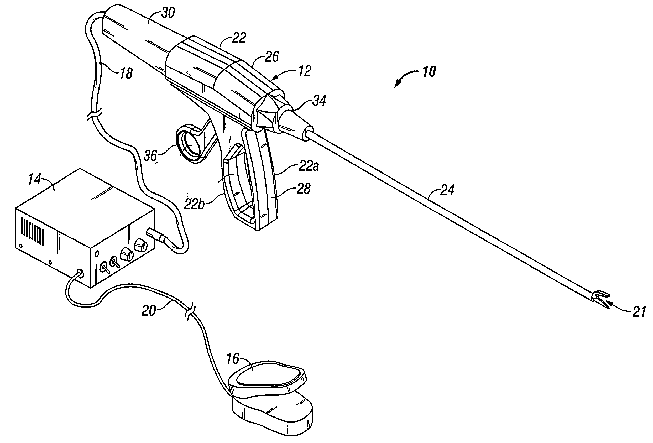
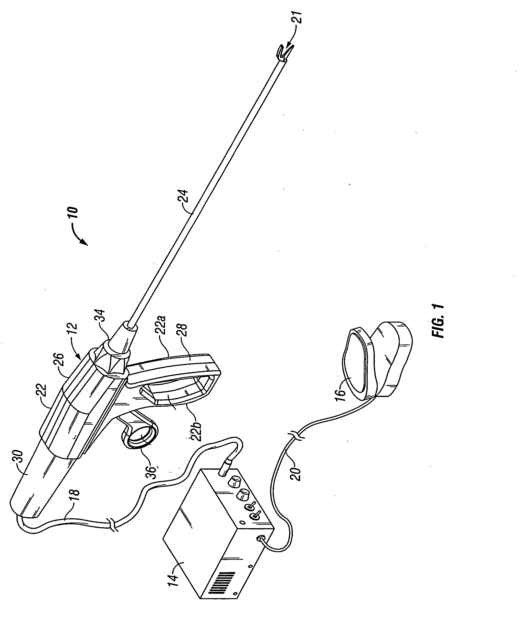
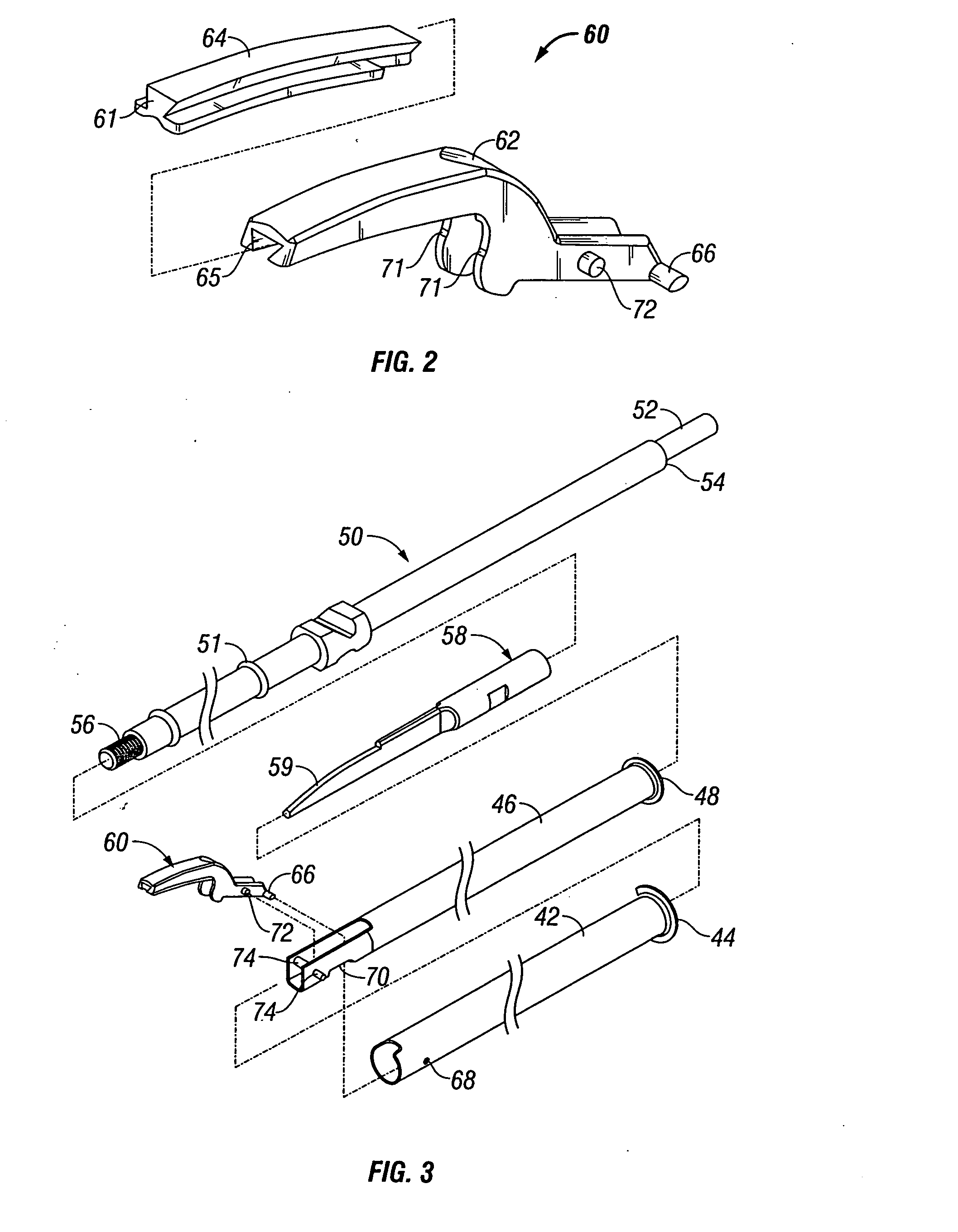
[0039]With reference to the first embodiment, the actuator tube 46 as well as the ultrasonic probe 21 are not in physical contact during normal operation of the instrument 10 (e.g., when the ultrasonic probe 21 is not overstressed). In addition, the actuator tube 46 and the ultrasonic probe 21 are electrically isolated because they are kept separate by silicon rings 51. As a result, the detection circuit 200 is open and the alarm indicator 204 is not active during normal operation of the instrument 10.

[0040]With reference to FIG. 6, when the ultrasonic probe 21 is overstressed it comes in contact with the inner surface of the actuator tube 46. During normal operation, the ultrasonic probe 21 is separated from the actuator tube 46 by a gap distance A and gap distance B on the bottom and top portions of the actuator tube 46, respectively. The gap distances A, B can be from about 1 mm to about 4 mm. Once the ultrasonic probe 21 is overstressed the ultrasonic probe 21 contacts the inner...

second embodiment

[0042]With reference to the second embodiment, the contact structure 201 and the ultrasonic probe 21 are not in physical contact during normal operation of the ultrasonic probe 21 and are, thus, electrically isolated from one another. When the ultrasonic probe 21 is overstressed (e.g., the probe 21 is operating outside the normal parameters) this may result in oscillation movements which are outside the normal range. Overstress may be also the result of a large moment exerted on the probe. During the normal operation, the maximum range to which the ultrasonic probe 21 may tilt is expressed by the gap distance C, the distance between the ultrasonic probe 21 and the contact structure 201, which is from about 1 millimeter to about 4 millimeters. The normal operational parameters are surpassed when the ultrasonic probe 21 is overstressed, thus, the ultrasonic probe 21 tilts toward the contact structure 201, closing the gap distance C at a point 206c. The detection circuit 200 also close...


PUM


Abstract

An ultrasonic surgical instrument having a deflection detection circuit is disclosed. The instrument includes an ultrasonic probe configured to conduct electricity and positioned a predetermined distance from one or more tubes. The ultrasonic probe is adapted to be operatively connected to an ultrasonic generator for vibration. The instrument also includes a deflection detection circuit having a secondary power source and an indicator, the power source is configured to supply electrical current to the tube, the probe, and the indicator, wherein the circuit is configured to close in response to the probe contacting the tube when the probe is deflected toward the tube thereby activating the indicator.

Description

BACKGROUND[0001]1. Technical Field[0002]The present disclosure relates generally to an ultrasonic dissection and coagulation system for surgical use. More specifically, the present disclosure relates to an ultrasonic instrument including a detection circuit for detecting deflection of an ultrasonic probe.[0003]2. Background of Related Art[0004]Ultrasonic instruments for surgical use and the benefits associated therewith are well known. For example, the use of an ultrasonic generator in conjunction with a surgical scalpel facilitates faster and easier cutting of organic tissue and accelerates coagulation. Improved cutting results from increased body tissue to scalpel contact caused by the high frequency of vibration of the scalpel blade with respect to body tissue. Improved coagulation results from heat generated by contact between the scalpel blade and the body tissue as the scalpel blade is vibrated at a high frequency.[0005]Conventional ultrasonic instruments include a variety of ...

Claims


Application Information

Patent Timeline
Patent Type & Authority Applications(United States)
IPC IPC(8): A61B17/32
CPCA61B17/22004A61B17/320068A61B17/320092A61B19/46A61B2017/0003A61B2017/00119A61B2017/293A61B2017/2929A61B2017/320072A61B2019/461A61B2019/465A61B2019/4857A61B2017/00734A61B90/06A61B2090/061A61B2090/065A61B2090/0811A61B2017/320069A61B2017/320094A61B2017/320095
Inventor BLIER, KENNETH
Owner TYCO HEALTHCARE GRP LP
Why Eureka
Try Eureka