Gas turbine engine assembly and methods of assembling same

a technology of gas turbine engines and assembly methods, which is applied in the direction of combination engines, machines/engines, mechanical equipment, etc., can solve the problems of increasing the overall cost, design complexity, and weight of the gas turbine engine, and operating the fan at a relatively slow speed may be detrimental to the operation of the booster compressor

Inactive Publication Date: 2008-05-01
GENERAL ELECTRIC CO
View PDF23 Cites 82 Cited by
  • Summary
  • Abstract
  • Description
  • Claims
  • Application Information

AI Technical Summary

Benefits of technology

[0004]In one aspect, a method of assembling a gas turbine engine is provided. The method includes coupling a low-pressure turbine to the core gas turbine engine, coupling a booster compressor to a gearbox, and coupling the gearbox to the low-pressure turbine such that the booster compressor is driven by the low-pressure turbine.

Problems solved by technology

However, operating the fan at a relatively slow speed may be detrimental to the operation of a booster compressor.
As such, additional booster stages may be required in order to produce the desired overall pressure ratio, thus increasing the overall cost, design complexity, and weight of the gas turbine engine.

Method used


Image

  • Gas turbine engine assembly and methods of assembling same
  • Gas turbine engine assembly and methods of assembling same
  • Gas turbine engine assembly and methods of assembling same

Examples


Embodiment Construction

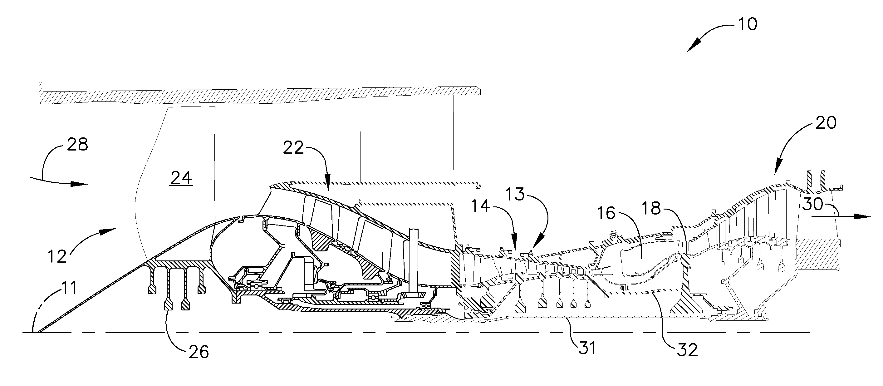
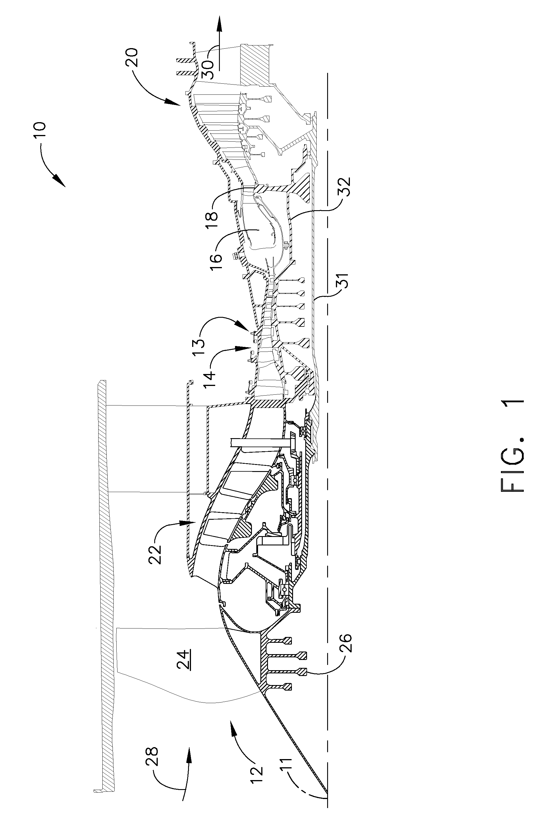
[0009]FIG. 1 is a schematic illustration of an exemplary gas turbine engine assembly 10 having a longitudinal axis 11. Gas turbine engine assembly 10 includes a fan assembly 12, and a core gas turbine engine 13 that includes a high-pressure compressor 14, a combustor 16, and a high-pressure turbine 18. In the exemplary embodiment, gas turbine engine assembly 10 also includes a low-pressure turbine 20 and a multi-stage booster compressor 22.

[0010]Fan assembly 12 includes an array of fan blades 24 extending radially outward from a rotor disk 26. Gas turbine engine assembly 10 has an intake side 28 and an exhaust side 30. Fan assembly 12 and low-pressure turbine 20 are coupled together via a gearbox 100 driven by a first rotor shaft 31, and compressor 14 and high-pressure turbine 18 are coupled together by a second rotor shaft 32.

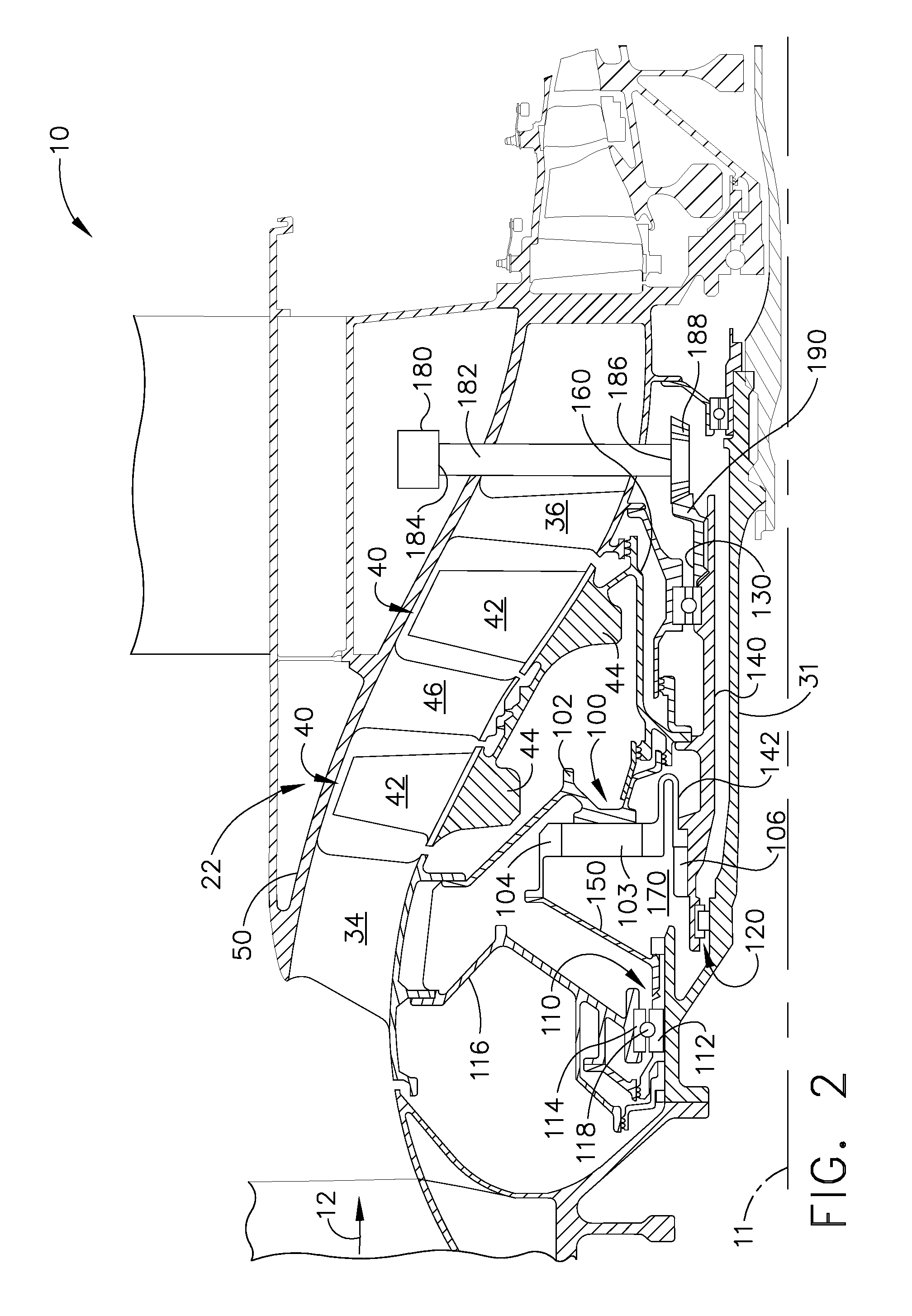
[0011]FIG. 2 is an enlarged cross-sectional view of a portion of the turbine engine assembly shown in FIG. 1. As shown in FIG. 2, booster 22 includes a plural...


PUM


Abstract

A method of assembling a gas turbine assembly includes providing a core gas turbine engine including a high-pressure compressor, a combustor, and a turbine, coupling a low-pressure turbine to the core gas turbine engine, coupling a booster compressor to a gearbox, and coupling the gearbox to the low-pressure turbine such that the booster compressor is driven by the low-pressure turbine.

Description

BACKGROUND OF THE INVENTION[0001]This invention relates generally to gas turbine engines, and more specifically to gas turbine engine assemblies and methods of assembling the same.[0002]At least some known gas turbine engines include a fan assembly, a core engine, and a low-pressure or power turbine. The core engine includes at least one compressor, a combustor, and a high-pressure turbine that are coupled together in a serial flow relationship. Air entering the core engine is mixed with fuel and ignited to form a high energy gas stream. The high energy gas stream flows through the high-pressure turbine to rotatably drive the high-pressure turbine and thus the compressor via a first drive shaft. The gas stream further expands through the low-pressure turbine, which rotatably drives the fan assembly through a second drive shaft.[0003]To improve engine efficiency, it is desirable to operate the fan assembly at a relatively lower speed than the operating speed of the high-pressure turb...

Claims


Application Information

Patent Timeline
Patent Type & Authority Applications(United States)
IPC IPC(8): F02K3/02
CPCF01D15/12Y02T50/671F02K3/072F02K3/06Y02T50/60
Inventor ORLANDO, ROBERT JOSEPHMONIZ, THOMAS ORYSCHILLING, JAN CHRISTOPHER
Owner GENERAL ELECTRIC CO
Why Eureka
Try Eureka