

Rolled copper foil and manufacturing method thereof
a technology of rolling copper foil and manufacturing method, applied in the field of rolling copper foil, can solve problems such as product failure, and achieve the effect of excellent flexible fatigue property and excellent flexible fatigue property
- Summary
- Abstract
- Description
- Claims
- Application Information
AI Technical Summary
Benefits of technology
Problems solved by technology
Method used
Image

Examples
first embodiment
of the Invention
(Ratio of Normalized Average Intensity)
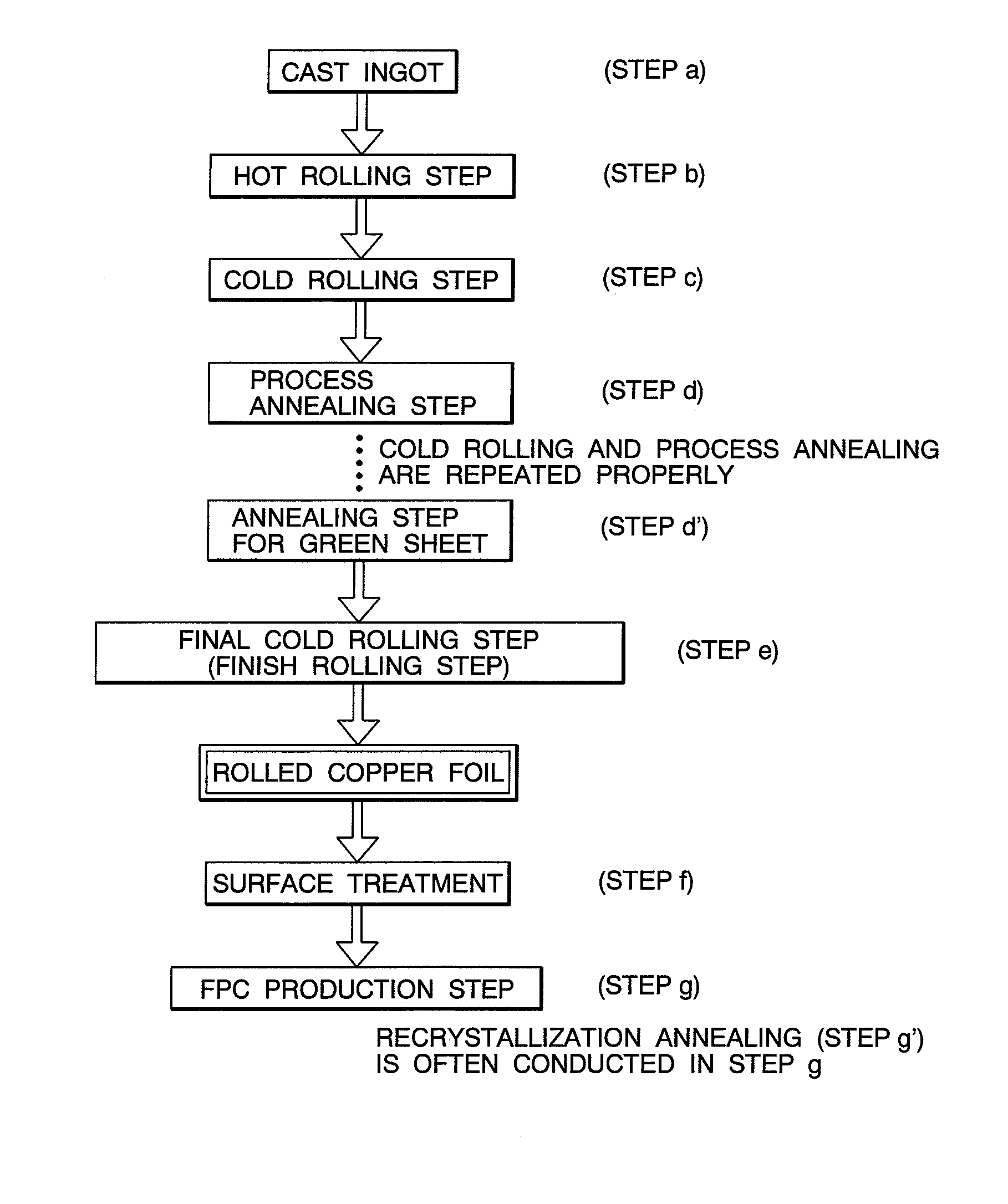
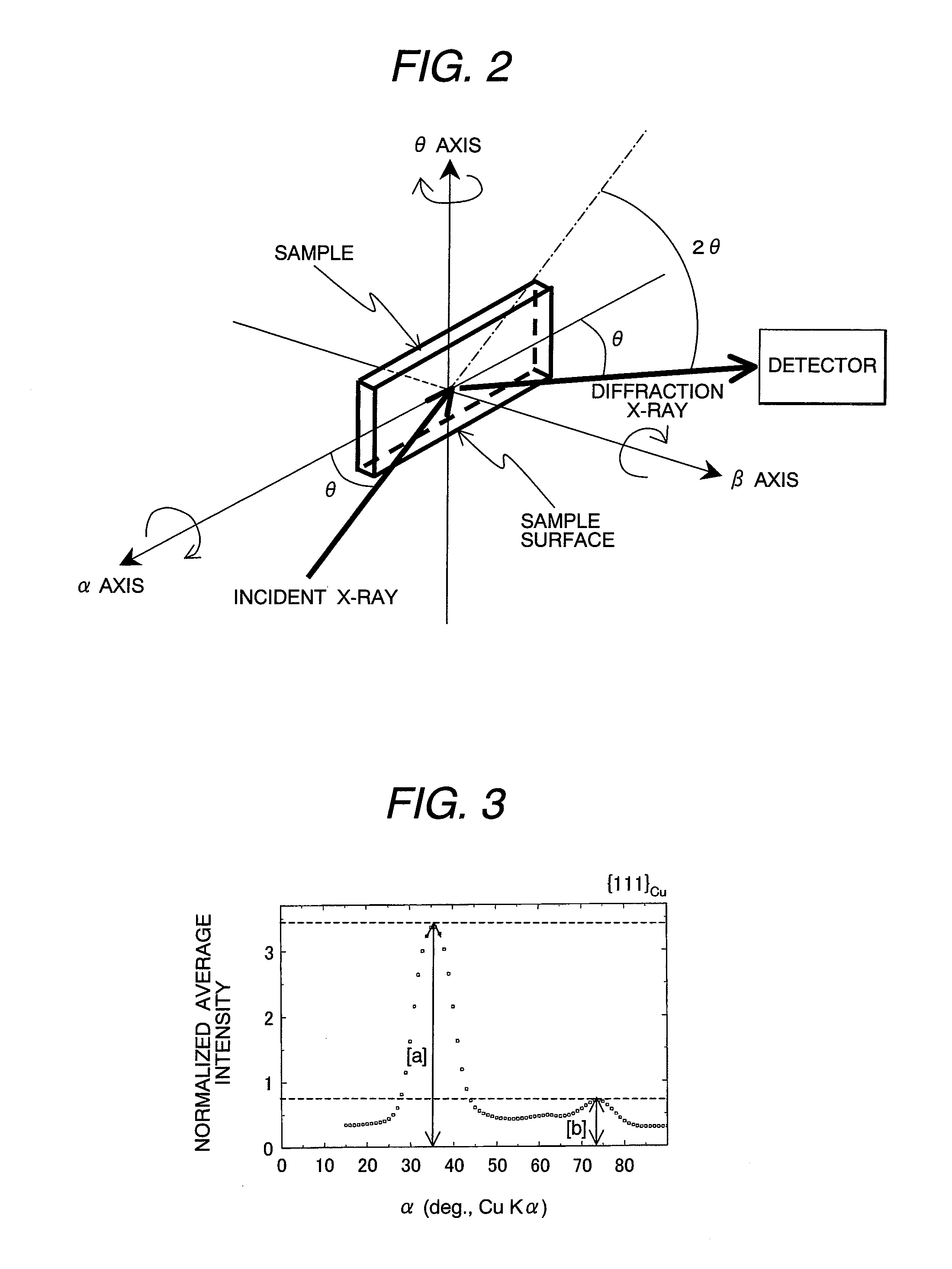
[0060]A rolled copper foil of this embodiment has a feature that a rolled copper foil is applied with a recrystallization annealing after a final cold rolling step, and that a crystal grain alignment thereof satisfies a ratio of [a] / [b]≧3 where [a] and [b] are normalized average intensities of a {111}Cu plane diffraction of a copper crystal by β-scanning at α=35° and 74°, respectively, in an XRD pole figure measurement to a rolled surface.
[0061]The normalized average intensity Rc means herein a number of counts averaging a diffraction intensity of a predetermined {hkl}Cu plane by β-axis scanning (in-plane rotation axis scanning) at respective angles α in the XRD pole figure measurement, which can be calculated according to the following equation (refer to the following literature for the details). Normalizing calculation is usually conducted by a computer.
Rc=Ic / Istd
in which
[0062]Ic: corrected intensity (background correction, a...
second embodiment
of the Invention
(In-Plane Alignment Measurement)
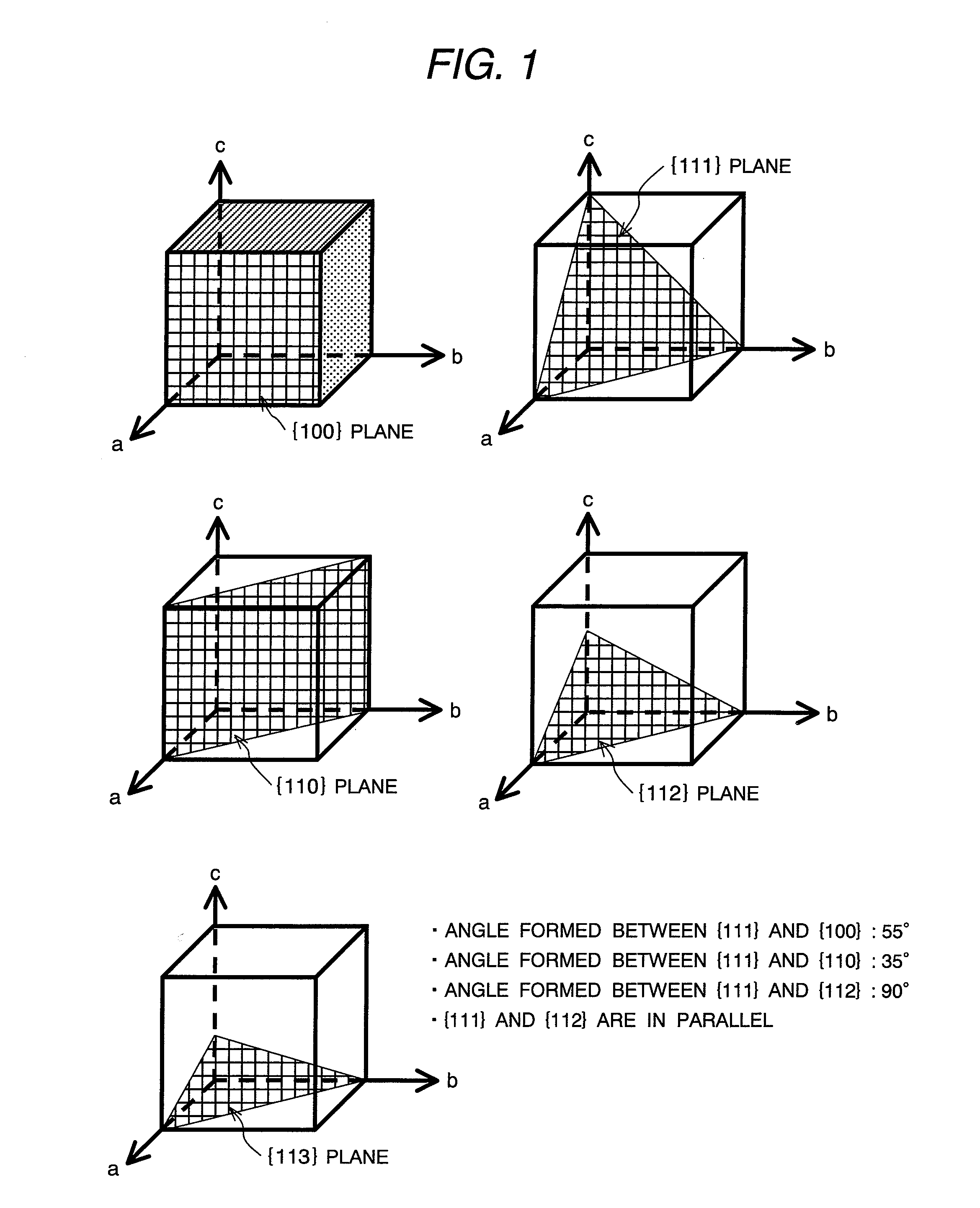
[0072]The rolled copper foil in this embodiment has a feature that an average of full width at half maximum of diffraction peaks (ave-FWHM{111}) of the {111}Cu plane in geometrical correlation with the {200}Cu plane of the rolled surface is 100 or less in the XRD in-plane alignment measurement, wherein the {111}Cu plane is in ageometrical relation of 55° with the {200}Cu plane of a cubic texture, in addition to a first embodiment of the invention.
[0073]FIG. 4 shows an example of a diffraction pattern indicating an in-plane alignment of the {111}Cu plane, which is in a geometrical relation of 55° (α=35° of measuring condition) to the {200}Cu plane, by the XRD in-plane alignment measurement to a rolled surface on a rolled copper foil applying a recrystallization annealing after a final cold rolling step in a preferred embodiment according to the invention. As shown in FIG. 4, four diffraction peaks, i.e., fourfold symmetric peaks can be ...
third embodiment
of the Invention
(2θ / θ Measurement)
[0075]The rolled copper foil in this embodiment has a feature that 90% or more of diffraction peak of a copper crystal is the {200}Cu plane diffraction in the XRD 2θ / θ measurement, in addition to a first embodiment of the invention.
[0076]FIG. 5 shows an example of a diffraction pattern by the XRD 2θ / θ measurement to the rolled surface on the rolled copper foil applying a recrystallization annealing after a final cold rolling step in a preferred embodiment according to the invention. As shown in FIG. 5, the rolled surface is strongly oriented to the {200}Cu plane of the recrystallized grains and the occupation ratio of the {200}Cu plane thereof is 90% or more. This result shows that the rolled copper foil has a well-developed cubic texture.
[0077]On the other hand, in a case where the occupation ratio of the {200}Cu plane diffraction among the diffraction peaks is less than 90%, no higher flexible fatigue property than usual can be obtained. According...
PUM
| Property | Measurement | Unit |
|---|---|---|
| Grain size | aaaaa | aaaaa |
| Fraction | aaaaa | aaaaa |
| Fraction | aaaaa | aaaaa |
Abstract
Description
Claims
Application Information