Planar coil component, method for winding end connection thereof and resonance transformer

a technology of resonance transformer and coil component, which is applied in the direction of coils, transformers/inductance details, inductances, etc., can solve the problems of reducing the height of products, affecting and requiring an excessive height of a bundled part of the terminal, so as to achieve the effect of reducing the height of the bundled part and improving the heat dissipation

Inactive Publication Date: 2008-05-01
TDK CORPARATION
View PDF6 Cites 24 Cited by
  • Summary
  • Abstract
  • Description
  • Claims
  • Application Information

AI Technical Summary

Benefits of technology

[0017]Under such circumstances, the first object of the invention is to provide a planar coil component, a method for winding end connection thereof and a resonance transformer, which does not require winding end bundling operation, can lower a height thereof even when using a thick litz wire etc. and can improve heat dissipation.

Problems solved by technology

(1) When binding the winding ends to the terminal sticking out from a bottom surface of the terminal board an excessive height for a bundled part of the terminal is required and it hinders lowering the height of products.
(2) In order to lower the height of products, a structure using L-pin type terminals with the winding ends bundled and soldered to the flat part of the L-pin type terminals is well known. But when binding and soldering litz wires, stranded wires or parallel wires in a contiguous terminal structure, adjacent bundled up portions of the wires are easily short-circuited in case of soldering. It causes a reduction in quality and reliability, and workability of the soldering also deteriorates.
(3) In order to lower the height of products, even when using L-pin type terminals, the bundled up portion where litz wires, stranded wires or parallel wires bind is of a considerable size. Thus lowering the height of the products is problematic. Even when binding the winding end to a horizontal part of the terminal, it is still necessary to make the terminal board thicker (or make a standoff larger) so that the bundled portion does not stick out from an underside of the terminal board.
(4) When a litz wire, a stranded wire or a parallel wire used for large current is bundled to a pin terminal, there have been problems in workability and quality (a bundled part may be unraveled easily until soldering etc.) because wires are wound on a bobbin and wire ends dispersed to each pin.
(5) When a litz wire, a stranded wire or a parallel wire used for large current is bound and soldered to a pin terminal, it is difficult to form an alloy layer of solder and copper of a winding (it is difficult for soldering that the solder soaks into bundles of thin copper wires). Thus, soldering workability and quality have been problematic.
(6) When a litz wire, a stranded wire or a parallel wire is wound around a bobbin and bundled to terminals, the wire the length of which is for bundling is wasted.
After the bobbin is mounted to a device board, the terminal is sandwiched between the device board and terminals board of the bobbin, thus it is difficult to dissipate heat from the terminals.
When a large current flows through the winding, a problem of heat generation between the terminal and the winding end occurs.
The structure does not solve the problems.
(2) The terminal board of the bobbin and the terminal structure correspond to a vertical type transformer (a magnetic core stands vertically with respect to a mounting surface), therefore, the structures are unsuitable for a horizontal type low height transformer i.e., a planar transformer (a magnetic core is parallel to a mounting surface).
(3) Secondary terminals are important for a resonance transformer but there is no ingenious design for secondary terminals disclosed in Patent Document 1.

Method used


Image

  • Planar coil component, method for winding end connection thereof and resonance transformer
  • Planar coil component, method for winding end connection thereof and resonance transformer
  • Planar coil component, method for winding end connection thereof and resonance transformer

Examples


Embodiment Construction

[0037]The invention will be described by reference to a preferred embodiment. This does not intend to limit the scope of the present invention, but to exemplify the invention.

[0038]The preferred embodiment according to the invention relates to a planar coil component, method for winding end connection thereof and resonance transformer.

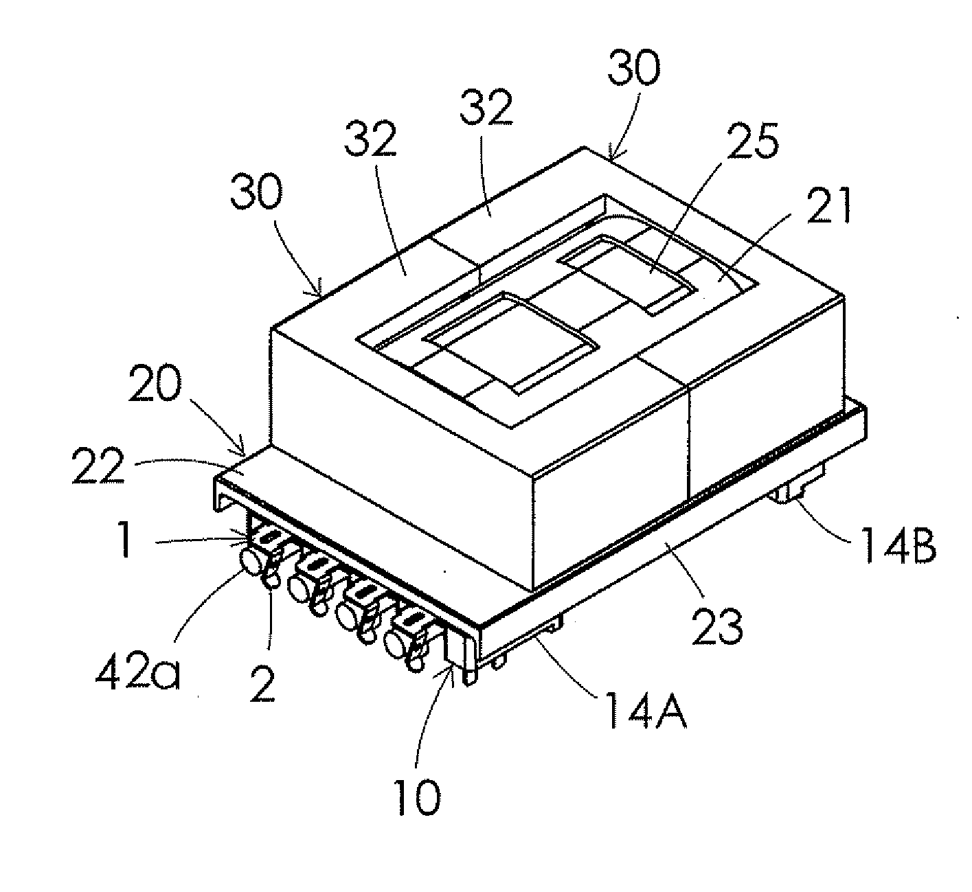
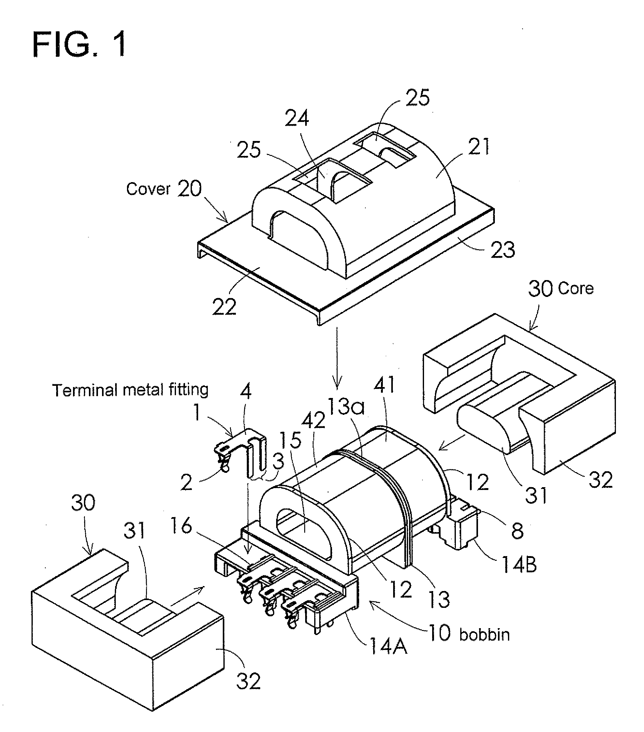
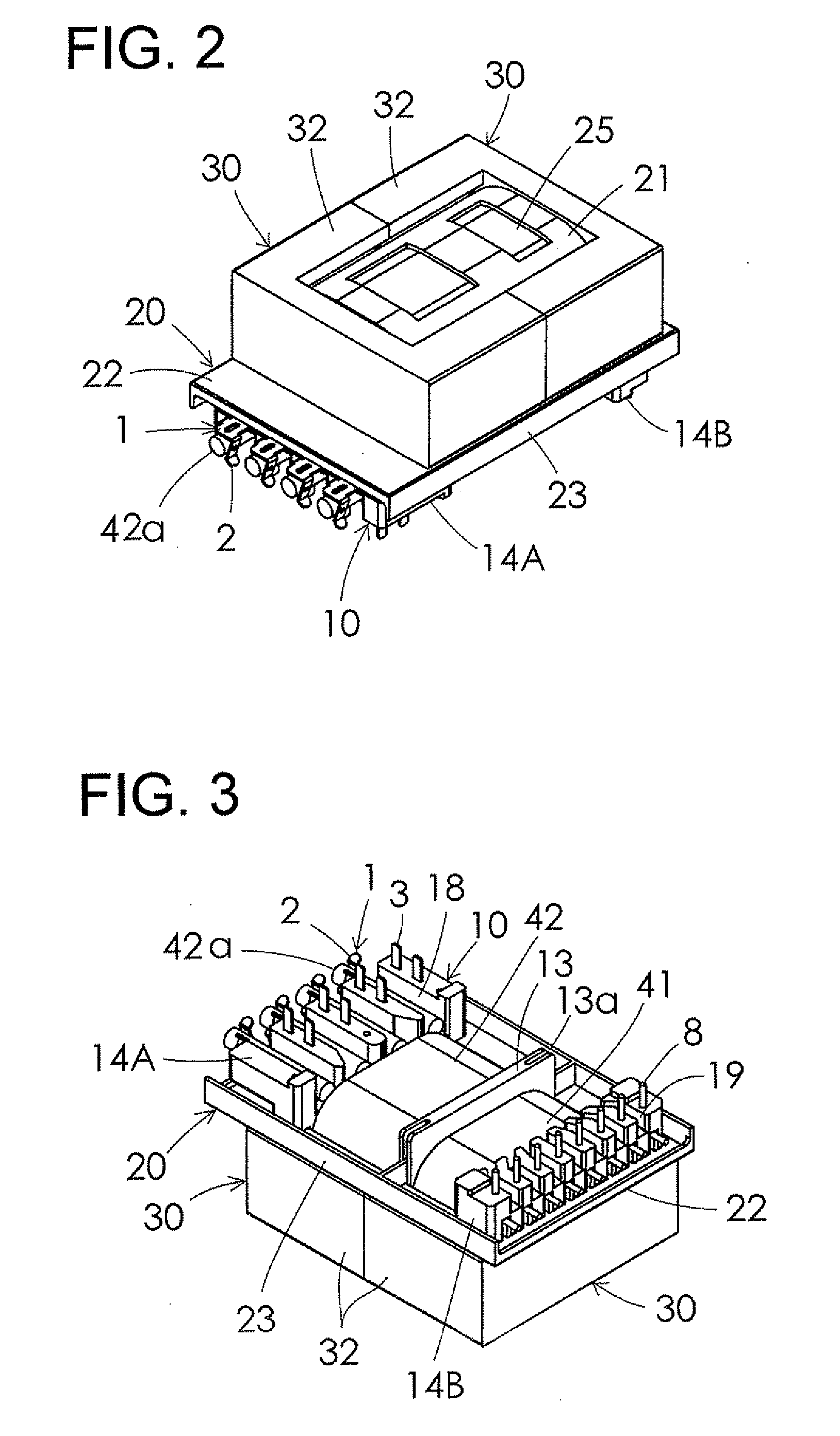
[0039]FIGS. 1 through 3 show the entire structure of a planar coil component, FIG. 4 shows a terminal metal fitting used therein, and FIGS. 5 through 7 show a bobbin with the terminal metal fittings installed.

[0040]The planar coil component in FIGS. 1, 2 and 3 is, as an example, constructed as a large current planar transformer suitable as a resonance transformer used in resonance type power supplies, and comprises a bobbin 10 in which a terminal metal fining 1 is installed, an insulation cover 20 mounted on the bobbin 10 after winding on the bobbin 10 and a pair of E-type cores 30 as magnetic cores attached to the bobbin 10 in a horizontal arrangement...


PUM

PropertyMeasurementUnit
heightaaaaaaaaaa
workabilityaaaaaaaaaa
sizeaaaaaaaaaa

Abstract

A planar coil component includes terminal metal fittings that include a crimping part, a terminal parts and a junction, and a bobbin on which a winding is wound. The bobbin has a terminal board including insertion holes. The terminal part is inserted from an upper surface of the terminal board into the insertion holes with the junction exposed, so that the terminal part projects from a bottom surface of the terminal board, each end of the winding is inserted into the crimping part through a slot in the bottom surface of the terminal board, and crimped. The winding is one of a litz wire, a stranded wires and a parallel wire, and welded at an end tip and connected to the terminal metal fitting.

Description

BACKGROUND OF THE INVENTION[0001]1. Field of the Invention[0002]The present invention relates to a planar coil component used as a large current planar transformer (e.g., a resonance transformer used in a resonance type power supply) or as a choke coil etc., to a method for winding end connection thereof and to a resonance transformer.[0003]2. Description of the Related Art[0004]Thin planar transformers are required for power supplies used in such devices as flat panel televisions etc. Because of the large amount of current in resonance transformers, litz wire, stranded wire or parallel wire etc. where multiple wires thickly bundled together, are used for windings. Generally the process for connecting winding ends to the terminals involves binding and soldering the winding ends of a litz or stranded wire etc. to the terminals (pin terminals) disposed on a terminal board of a bobbin. However, the process has the following problems.[0005](1) When binding the winding ends to the termin...

Claims


Application Information

Patent Timeline
Patent Type & Authority Applications(United States)
IPC IPC(8): H01F27/29
CPCH01F5/02H01F5/04H01F2005/043H01F27/29H01F38/02H01F27/2828
Inventor YAMAGUCHI, KENICHIIWAKURA, MASAAKIKURAMOCHI, TORU
Owner TDK CORPARATION
Why Eureka
Try Eureka