Switching power supply unit

a power supply unit and power supply technology, applied in emergency power supply arrangements, battery/fuel cell control arrangements, instruments, etc., to achieve the effect of reducing power loss during switching operation

Active Publication Date: 2008-05-01
TDK CORPARATION
View PDF2 Cites 61 Cited by
  • Summary
  • Abstract
  • Description
  • Claims
  • Application Information

AI Technical Summary

Benefits of technology

[0013]In the switching power supply unit of an embodiment of the invention, preferably, the switching control section performs control such that the first switching circuit performs switching operati

Problems solved by technology

However, in the Japanese Unexamined Patent Publication No. 8-317508, no description was made on a specific

Method used


Image

  • Switching power supply unit
  • Switching power supply unit
  • Switching power supply unit

Examples


first embodiment

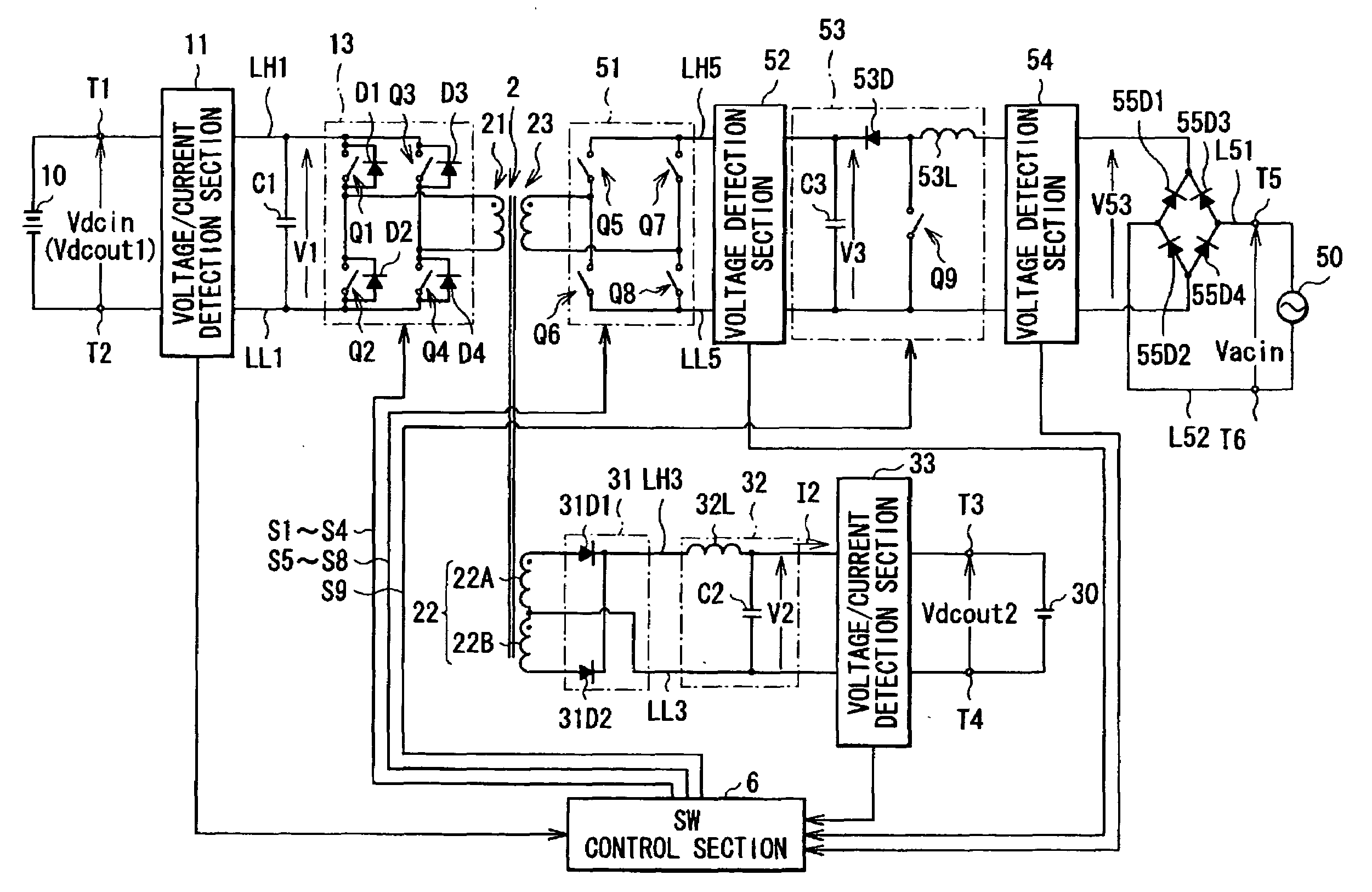
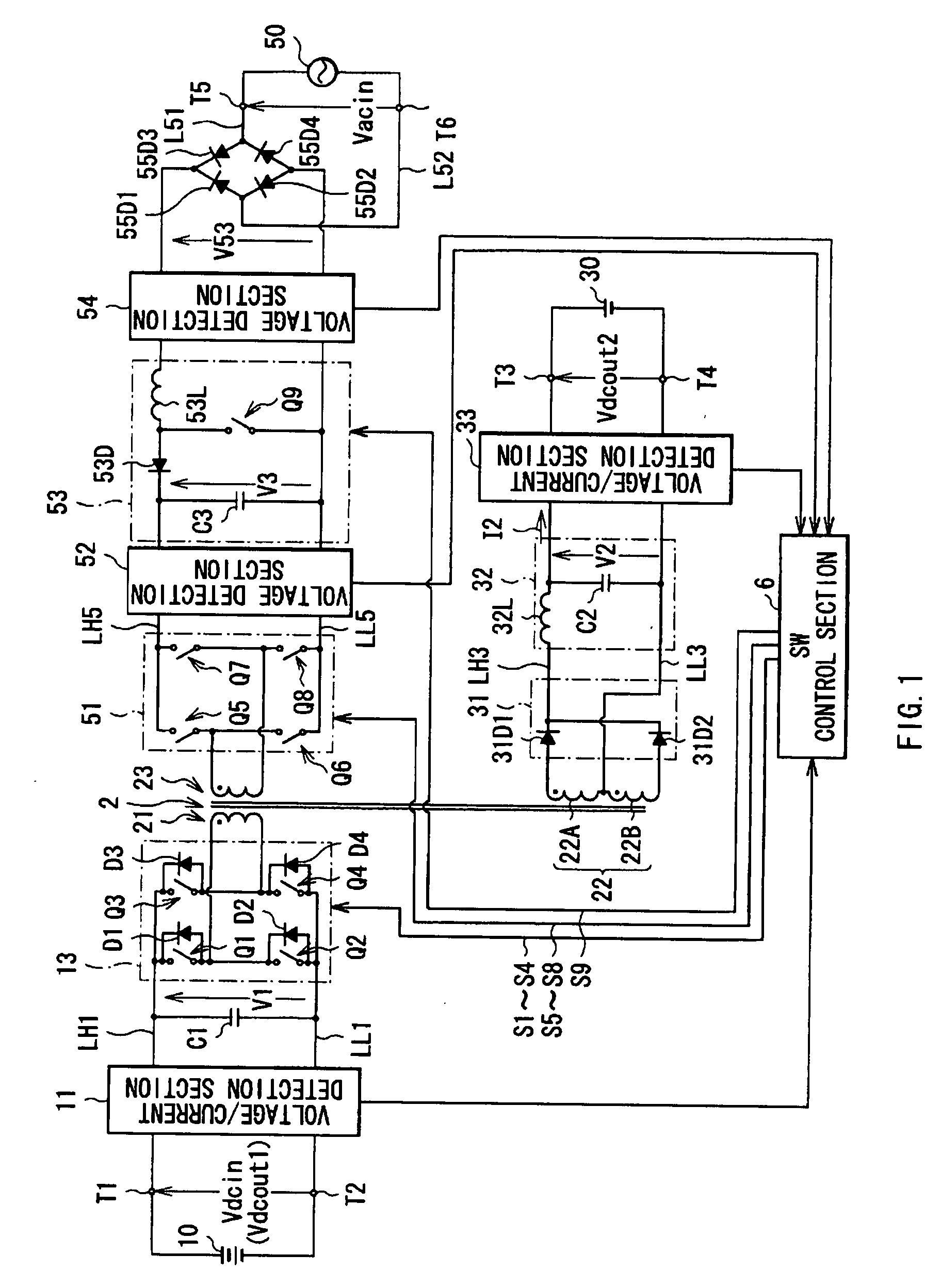
[0033]FIG. 1 shows a circuit configuration of a switching power supply unit according to a first embodiment of the invention. The switching power supply unit is applied to a car and the like, and has a transformer 2, a voltage / current detection section 11, a capacitor C1, and a bidirectional switching circuit 13, those being provided at a side of a main battery 10 described later with respect to the transformer 2, and a rectifier circuit 31, a smoothing circuit 32, a voltage / current detection section 33, a switching circuit 51, voltage detection sections 52 and 54, a PFC (Power Factor Correction) circuit 53, and diodes 55D1 to 55D4, and a SW control section 6 for controlling switching operation by the bidirectional switching circuit 13, switching circuit 51, and PFC circuit 53, those being provided at respective sides of an accessory battery 30 and a commercial power supply 50 described later with respect to the transformer 2.

[0034]The capacitor C1 is disposed between a high voltage...

second embodiment

[0098]Next, a second embodiment of the invention is described. A switching power supply unit of the embodiment is different from the switching power supply unit of the first embodiment in substance of the accessory-battery-prioritized charge operation. The same components as those shown in the first embodiment are marked with the same references, and appropriately omitted to be described.

[0099]FIG. 12 shows in a flowchart detail of the accessory-battery-prioritized charge operation (corresponding to the step S115 shown in FIG. 2) in the switching power supply unit according to the embodiment. FIGS. 13A to 13E are waveforms of operation of respective circuits in the accessory-battery-prioritized charge operation in the embodiment (specifically, operation before the voltage V3 between both ends of the capacitor C3 is generated based on the AC input voltage Vacin), wherein FIG. 13A shows the AC input voltage Vacin, FIG. 13B shows an input voltage into the PFC circuit 53 (output voltage...


PUM


Abstract

Provided is a switching power supply unit being able to perform voltage conversion between two DC power supplies, and perform appropriate charge operation based on an inputted AC voltage. When a main battery is preferentially charged, an SW control section performs control such that a duty ratio is fixed in switching operation of a switching circuit, and a duty ratio is variable in switching operation of a bidirectional switching circuit. On the other hand, when an accessory battery is preferentially charged, the SW control section performs control such that a duty ratio is variable in switching operation of each of the switching circuit and the bidirectional switching circuit. When the accessory battery is preferentially charged, the SW control section may perform control such that the duty ratio is fixed in switching operation of the switching circuit, and a duty ratio is variable in switching operation of a switching element.

Description

BACKGROUND OF THE INVENTION[0001]1. Field of the Invention[0002]The present invention relates to a switching power supply unit configured to produce switching output obtained by switching a DC input voltage at an output winding of a power conversion transformer.[0003]2. Background Art[0004]Generally, an electric vehicle is equipped with a low voltage battery (accessory battery) for outputting a low DC voltage such as about 14 V as a power supply for driving in-vehicle instruments (accessories) such as a wiper, a headlight, a room light, an audio instrument, an air conditioner, and various measuring instruments, and equipped with a high voltage battery (main battery) for outputting a high DC voltage such as about 350 to 500 V as a power supply for driving a motor. Typically, charge operation to such a low voltage battery is performed by rectifying an AC output voltage from an AC generator driven in terms of rotation of an engine to obtain a high DC voltage, and converting such a DC i...

Claims


Application Information

Patent Timeline
IPC IPC(8): H02M3/335
CPCH02J1/08H02J7/0013H02J7/022H02J7/045Y02T10/7055H02J2001/008H02M3/33584H02M3/3376H02J7/085B60L1/003B60L1/02B60L2210/10B60L2240/529B60L2240/547B60L2240/527Y02T10/92Y02T10/7072Y02T90/14B60L53/14B60L53/22B60L58/20H02J1/082H02J7/02H02J2207/20H02J7/007182Y02T10/70Y02T10/72Y02T90/12
Inventor TAKAYANAGI, YOSHINOBUSATO, KUNIHIRO
Owner TDK CORPARATION
Why Eureka
Try Eureka