
System and method for symbol rate estimation using vector velocity

a vector velocity and symbol rate technology, applied in the field of signal processing, can solve problems such as ineffective existing methods of symbol rate estimation, impede symbol rate estimation using the known techniques, and suffer from various problems and limitations

Inactive Publication Date: 2008-05-01
L 3 COMM CORP
View PDF14 Cites 8 Cited by
  • Summary
  • Abstract
  • Description
  • Claims
  • Application Information

AI Technical Summary

Benefits of technology

[0009]Embodiments of the present invention provide an improved system and method of estimating a symbol rate of a symbol that does not suffer from the problems and limitations of the prior art. Particularly, embodiments of the present invention provide a system and method for estimating a symbol rate of a signal that does not require any prior knowledge of the signal's structure and is accurate in the presence of frequency offset and noise.

Problems solved by technology

Unfortunately, these methods suffer from various problems and limitations.
Thus, in situations where very little or nothing is known about the signal to be analyzed, existing methods of symbol rate estimation are of no use.
Furthermore, the presence of signal noise and frequency offset can impede symbol rate estimation using the known techniques.

Method used


Image

  • System and method for symbol rate estimation using vector velocity
  • System and method for symbol rate estimation using vector velocity
  • System and method for symbol rate estimation using vector velocity

Examples


Embodiment Construction

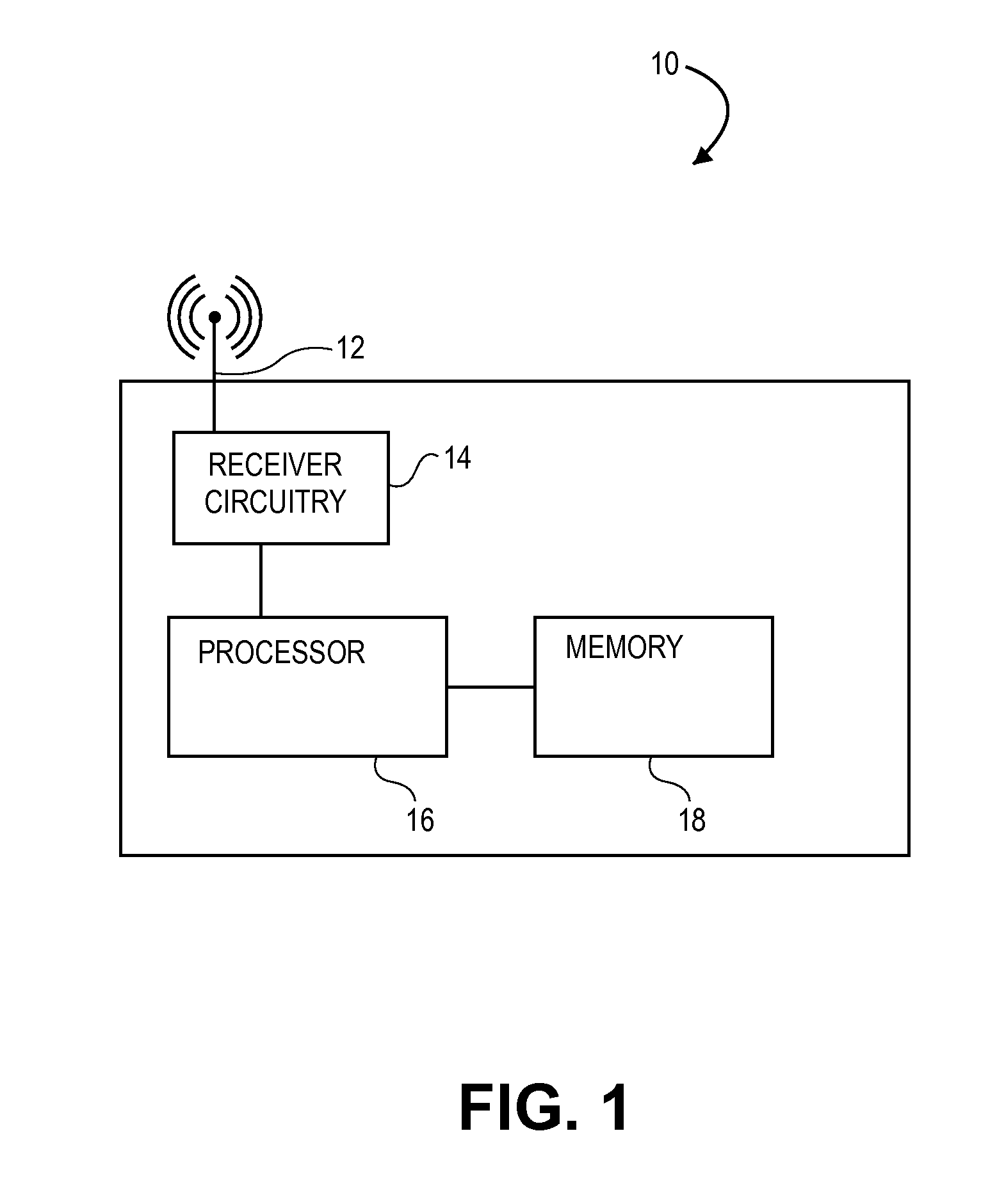
[0031]A receiver operable to estimate a symbol rate of a received signal according to principles of the present teachings is illustrated in FIG. 1 and designated generally by the reference numeral 10. The receiver 10 comprises an antenna 12, receiver circuitry 14, a processor 16, and a memory component 18. The receiver 10 may further include other conventional components not illustrated or described herein, such as, for example, a power supply and user interface elements.

[0032]The receiver circuitry 14 is operable to detect signals collected by the antenna 12 and condition the signals to be analyzed by the processor 16. The receiver circuitry 14 may convert signals received via the antenna 12 to digital format, generating a series of digital sample values representing the received signal. The receiver circuitry 14 may include circuitry adapted specifically for use with one or more particular encoding schemes. For example, it is common in quadrature phase shift keying to separate an ...


PUM


Abstract

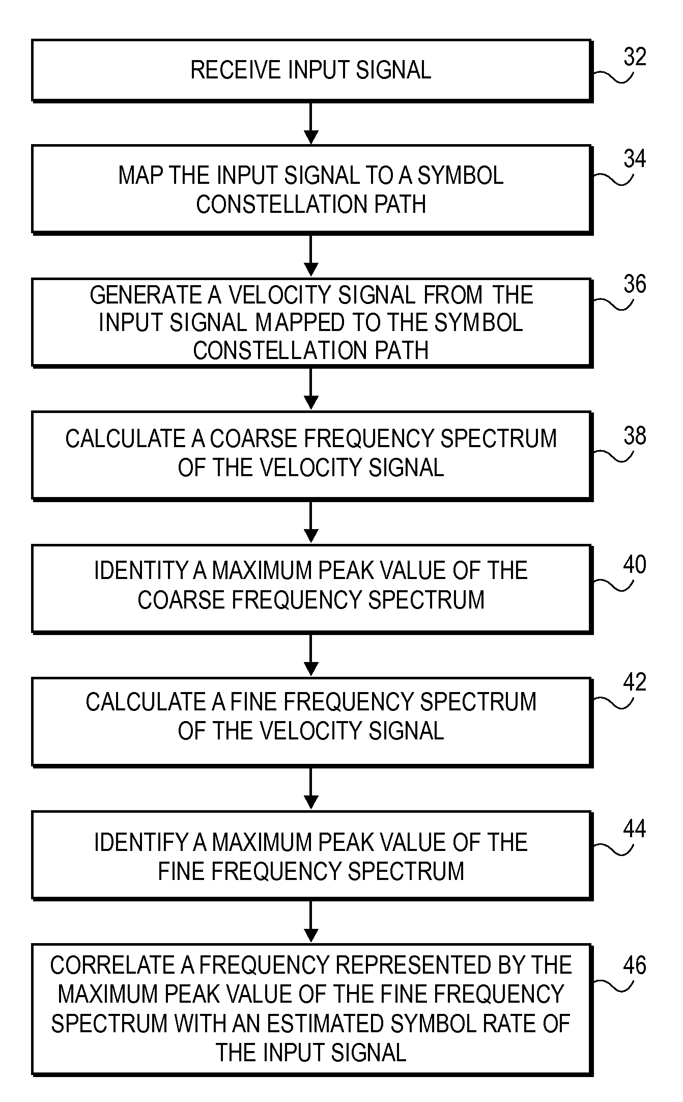
A system and method for symbol rate estimation using vector velocity that does not require any prior knowledge of the signal's structure and is accurate in the presence of frequency offset and noise. An input signal is converted to a symbol constellation path signal, and a velocity signal representing a velocity of the symbol constellation path signal is generated. A first frequency spectrum of the velocity signal is generated by performing a Fast Fourier transform on the velocity signal, and a maximum peak value of the first frequency spectrum, a first bin below the maximum peak value, and a second bin above the maximum peak value are identified. A Chirp-Z transform is performed on the velocity signal using the first bin and the second bin as coefficients, wherein performing the Chirp-Z transform generates a second frequency spectrum including only frequencies within the range of the first bin and the second bin, and wherein the second frequency spectrum presents a higher resolution than the first frequency spectrum. A maximum peak value of the second frequency spectrum is identified, wherein the maximum peak value of the second frequency spectrum corresponds to the symbol rate of the input signal.

Description

BACKGROUND OF THE INVENTION[0001]1. Field of the Invention[0002]Embodiments of the present invention relate to signal processing. More particularly, embodiments of the invention involve a system and method for estimating a symbol rate of a signal that does not require prior knowledge of the signal's structure and is accurate in the presence of frequency offset and noise.[0003]2. Description of Prior Art[0004]Signal modulation is the process of encoding a signal with information—such as voice, data, or an image—on a carrier signal, and demodulation is the process of recovering the information from the carrier signal at a signal receiver. Various modulation schemes are known, including amplitude modulation, frequency modulation, and phase modulation. In each modulation scheme, a given state of the carrier signal representing one or more bits of data is commonly referred to as a “symbol.”[0005]By way of example, phase modulation, commonly referred to as phase shift keying (PSK) in digi...

Claims


Application Information

Patent Timeline
Patent Type & Authority Applications(United States)
IPC IPC(8): H04K1/10
CPCH04L25/0262
Inventor JUDD, DARREL RAYTALBERT, JOSHUA DOUGLASMOSES, BRUCE OLIVER
Owner L 3 COMM CORP
Learn More