Machine tool having function of detecting contact between tool and workpiece

a technology of workpiece contact and machine tool, which is applied in the field of machine tools, can solve the problems of inability to detect the true position of the blade tip, the inability to accurately determine the position of the workpiece, and the inability to see the blade tip, so as to achieve the effect of greater susceptibility to external disturbances

Active Publication Date: 2008-05-01
FANUC LTD
View PDF12 Cites 10 Cited by
  • Summary
  • Abstract
  • Description
  • Claims
  • Application Information

AI Technical Summary

Benefits of technology

[0019]Servo gains of servo controllers for controlling the movable axes may be set to lower values to have greater susceptibility to external disturbances so that contact between the tool and the workpiece is detected with a smaller force exerted on the tool or the workpiece.
[0020]The machine tool may further comprise detecting means for detecting an abnormal increase of any of the position deviations, and the retreating means may retreat the tool from the workpiece when the abnormal increase is detected by the detecting means.
[0021]The detecting means may output a signal indicative of the movable axis on which the abnormal increase of the position deviation is detected.
[0022]In an ultra-precision machine tool comprised of frictionless movable axes supported by fluid bearings, even a slight force exerted on the movable parts causes the movable parts to move, which is used to detect an increase in position deviation. As a result, that portion which protrudes the most from a machining surface is detected simply by contact between the tool and the workpiece, and that contact point can be detected as the location of the machining start point.

Problems solved by technology

As a method that detects the position of the tool with respect to the workpiece, the position of the tool can be detected with the tool detection device used conventionally but the position of the workpiece cannot be ascertained accurately.
In addition, with a tool having a sharp tip, the true position of the tip cannot be detected.
However, given the limited focal depth of the microscope, as machining progresses sometimes the blade tip can no longer be seen.
As a result, even a slight force exerted on the movable axes, because the movable axes move, in a torque-over state like that described in JP2002-328707A, when a state is detected in which the position deviation has exceeded a predetermined value, the possibility increases that the workpiece or tool has already moved from a contact position for that workpiece and tool, making it difficult to determine that position with nano-unit accuracy.

Method used


Image

  • Machine tool having function of detecting contact between tool and workpiece
  • Machine tool having function of detecting contact between tool and workpiece
  • Machine tool having function of detecting contact between tool and workpiece

Examples


Embodiment Construction

[0029]A detailed description will now be given of one embodiment of the present invention, with reference to the drawings.

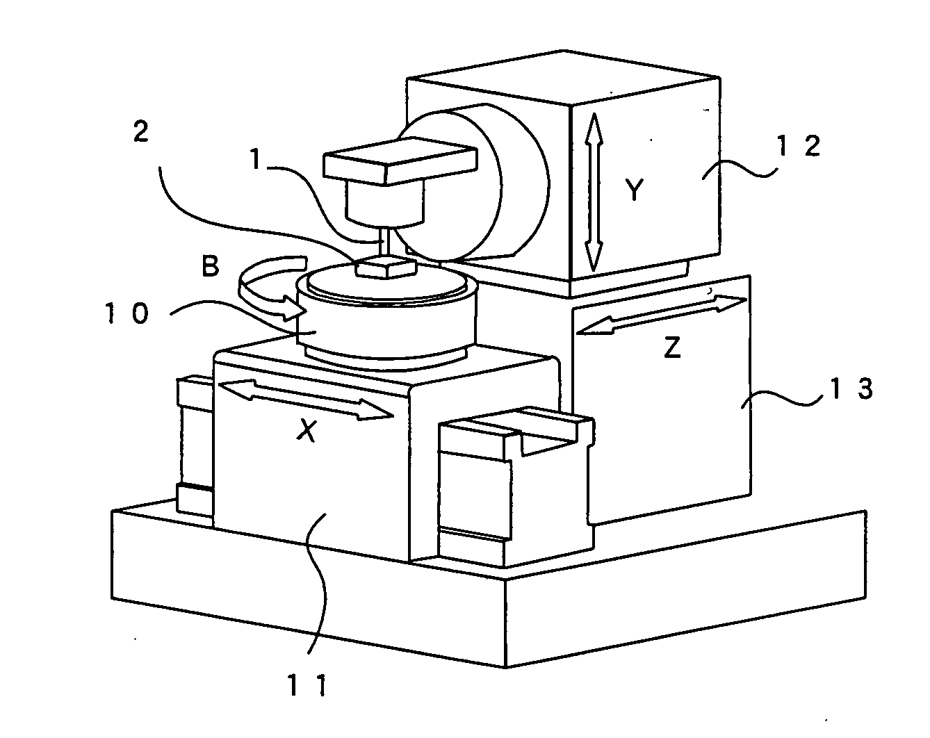
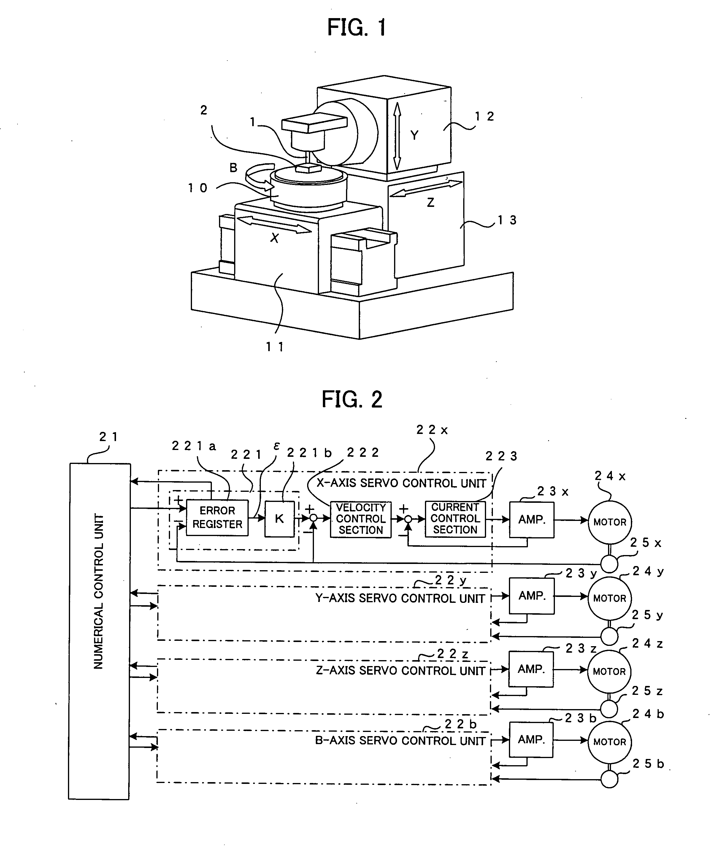
[0030]FIG. 1 is a schematic diagram of a machine tool that performs ultra-precise machining according to one embodiment of the present invention. In the present embodiment, as movable axes there are three linear motion axes (hereinafter “linear axes”) and one rotary axis. A rotary table 10 is mounted on an X-axis member 11, which is a linear axis driven in the direction of a horizontal direction X axis. The rotary table 10 rotates about a B axis, which is an axis disposed orthogonal to the X axis. A workpiece 2 that is an object to be machined is mounted on the rotary table 10. A tool 1 is mounted on a Y-axis member 12, which is a linear axis that moves in the direction of a Y axis parallel to the rotary B axis. Further, the Y-axis member 12 is mounted on a Z-axis member 13, which is a linear axis that moves in the direction of a Z axis orthogonal to the X axis a...


PUM

PropertyMeasurementUnit
velocityaaaaaaaaaa
forceaaaaaaaaaa
output torqueaaaaaaaaaa

Abstract

An ultra-precision machine tool capable of accurately detecting a machining start position, in which movable axes are supported by fluid bearings. A workpiece is mounted on a rotary table of a B axis, and the rotary table is mounted on an X axis that is a linear motion axis. A tool is mounted on a Y axis. The Y axis is mounted on a Z axis. The X axis is moved reciprocally each time the Z axis is moved a predetermined amount, a machining surface of the workpiece is scanned, and it is determined whether or not position deviation of the X, Y and B axes reaches or exceeds a reference value. The Y axis is driven and the tool is moved toward the workpiece a predetermined amount, and the above-described scan is performed. When the position deviation of the X, Y and B axes reaches or exceeds the reference value it is determined that contact between the tool and the workpiece has occurred, and this contact point is stored as the machining start position, the Y axis is skipped, and the tool is moved a predetermined amount in a direction away from the workpiece, thus enabling a point of maximum protrusion from the machining surface of the workpiece to be simply detected as the machining start point.

Description

BACKGROUND OF THE INVENTION[0001]1. Field of the Invention[0002]The present invention relates to a machine tool that performs ultra-precise machining for which machining accuracy in nano-units is required, and more particularly to a machine tool capable of accurately determining a machining start position.[0003]2. Description of Related Art[0004]In a machine tool that performs ultra-precise machining for which machining accuracy measured in nano-units is required, when performing scribing or the like on a machining surface, in order to improve machining accuracy it is necessary to determine a position of a tool tip point with respect to the workpiece accurately and start machining, and it is also necessary to set a coordinate position of the workpiece machining start point with nano-unit accuracy.[0005]Conventionally, the tool tip position is detected using a sensor or other such special tool detection device or a microscope. As methods of detecting the position of the workpiece, an...

Claims


Application Information

Patent Timeline
Patent Type & Authority Applications(United States)
IPC IPC(8): B23C9/00
CPCG05B19/4015G05B19/404G05B2219/37387Y10T409/500656G05B2219/50027Y10T409/3084Y10T409/500164G05B2219/37405B23Q17/2241
Inventor HON, YONPYOEBIHARA, KENZOKAWAI, TOMOHIKO
Owner FANUC LTD
Why Eureka
Try Eureka