Process of microwave brazing with powder materials

Inactive Publication Date: 2008-02-05
GENERAL ELECTRIC CO
View PDF21 Cites 34 Cited by
  • Summary
  • Abstract
  • Description
  • Claims
  • Application Information

AI Technical Summary

Benefits of technology

[0008]From the above, it can be appreciated that the process of this invention can be applied to various processes in which heating of a powdered material is desired, for example, the forming of coatings including the repair or build-up of a damaged surface and the metallurgical joining of components by brazing. Because heating is by microwave radiation, the heating rate and melting of the powder particles are influenced by susceptibility to microwave radiation instead of location relative to a heating source or relative to any surface contacted by the powder mass. With the addition of one or more constituents with greater susceptibility than the filler particles and / or the thermal pretreatment, greater susceptibility to microwave radiation can be induced in the powder mass to promote complete and rapid melting of the mass and its particles. This aspect of the invention enables the powder mass to melt prior to melting of a surface contacted by the region. As a result, the powder particles can be formed of an alloy having the same melting temperature (for example, within 150° C.) as the surface contacted by the powder mass.
[0009]Other objects and advantages of this invention will be better appreciated from the following detailed description.

Problems solved by technology

During engine operation, gas turbine engine components are subject to strenuous high temperature conditions under which various types of damage or deterioration can occur.
As examples, erosion and oxidation reduce wall thicknesses of turbine nozzles and vanes, and cracks can initiate at surface irregularities and propagate as a result of stresses that are aggravated by thermal cycling.
While widely employed to fabricate and repair gas turbine engine components, conventional brazing processes have notable disadvantages.
First, the entire component must be subjected to a vacuum heat treatment, which is a very lengthy process in a production environment, unnecessarily exposes undamaged regions of the component to high temperatures, and can potentially remelt joints in other sections of the component.
Furthermore, the braze alloy typically comprises elements similar to the base metal of the component, but with the addition of melting point suppressants (e.g., boron, silicon, etc.) that reduce its melting point below the base metal solidus temperature, thereby significantly altering its mechanical properties.
Drawbacks to this approach are lack of local heating of the braze alloy only, as an entire region of the component is inevitably heated, and significant heat loss from radiation in directions away from the intended brazement.
However, typical braze alloy compositions do not couple sufficiently with microwave energy to be melted, with the result that the braze alloy powder is instead sintered and as a result has properties greatly inferior to the base metal of the component.

Method used


Image

  • Process of microwave brazing with powder materials
  • Process of microwave brazing with powder materials
  • Process of microwave brazing with powder materials

Examples


Embodiment Construction

[0015]The invention will be described with specific reference to processing of components for a gas turbine engine, and particularly the fabrication and repair of such components with a braze material. However, the invention has application to a variety of components, materials, and processes other than those discussed, and such variations are within the scope of this invention.

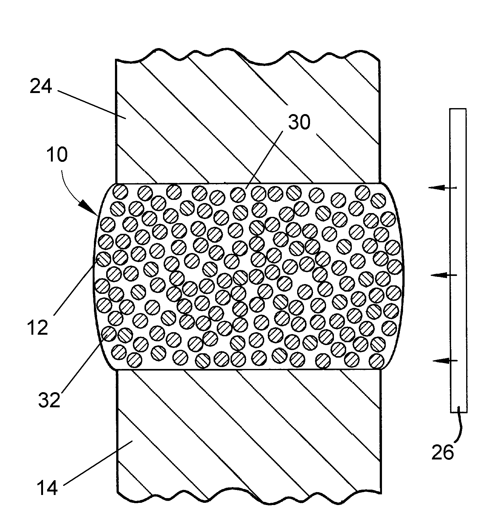
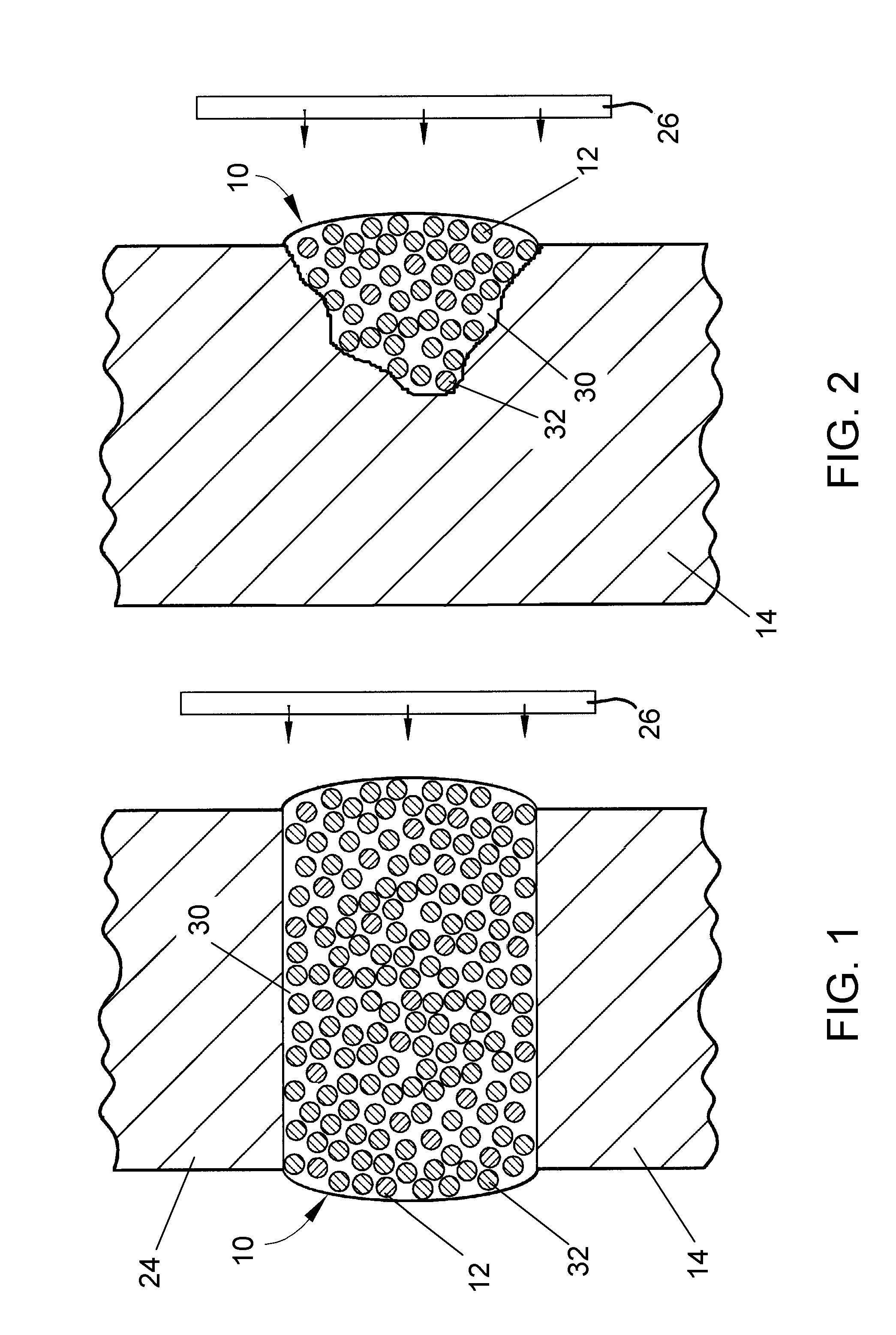
[0016]FIGS. 1 and 2 depict embodiments of this invention, in which consistent reference numbers are used to identify functionally similar structures. FIG. 1 schematically represents a mass 10 of filler metal particles 12 between and contacting opposing surfaces of two substrates 14 and 24 to be metallurgical joined by the particles 12, and FIG. 2 schematically represents a mass 10 of filler metal particles 12 within a defect in a surface of a substrate 14 for the purpose of repairing the surface. In both FIGS. 1 and 2, the particles 12 are shown as being contained within a binder 30 that, according to known b...


PUM

PropertyMeasurementUnit
Fractionaaaaaaaaaa
Percent by massaaaaaaaaaa

Abstract

A process for heating a powder material by microwave radiation so that heating of the powder material is selective and sufficient to cause complete melting of the particles. The process entails providing a mass of powder comprising a quantity of filler particles of a metallic composition, and subjecting the mass to microwave radiation so that the filler particles within the mass couple with the microwave radiation and are completely melted. According to one aspect, the mass further contains at least one constituent that is more highly susceptible to microwave radiation than the filler particles, and the filler particles are melted as a result of heating by microwave radiation and thermal contact with the at least one constituent. According to another aspect, the powder mass is thermally pretreated to induce an irreversible increase in its dielectric loss factor prior to melting by microwave irradiation.

Description

BACKGROUND OF THE INVENTION[0001]This invention generally relates to methods for heating powder materials, including processes and materials for use in the manufacturing, coating, repair, and build-up of superalloy components. More particularly, this invention relates to processes for significantly enhancing the melting of powders in a braze material by microwave energy.[0002]Nickel, cobalt, and iron-base superalloys are widely used to form high temperature components of gas turbine engines. While some high-temperature superalloy components can be formed as a single casting, others are preferably or required to be fabricated by other processes. As an example, brazing is widely used to fabricate gas turbine components, as in the case of high pressure turbine nozzle assemblies. Brazing techniques conventionally encompass joining operations performed at an elevated temperature but below the melting point of the metals being joined. In carrying out the brazing process, an appropriate br...

Claims


Application Information

Patent Timeline
IPC IPC(8): H05B6/64B23K35/32
CPCB23K1/005
Inventor CRETEGNY, LAURENTBUDINGER, DAVID EDWINNECULAES, VASILE BOGDANSHULMAN, HOLLY SUEFALL, MORGANA LYNNALLAN, SHAWN MICHAEL
Owner GENERAL ELECTRIC CO
Why Eureka
Try Eureka